Heidenhain to OPC-UA Bridge
This tutorial uses the Heidenhain Simulator and an OPC-UA server.
Preconditions
-
HumanOS IoT Designer installed on development client (Check Installation Manual)
-
HeidenhainDNC installed on the development client.
The HeidenhainDNC manages the connections to different Heidenhain Controllers.
Download the HeidenhainDNC here. -
Heidenhain Simulator for iTNC530 installed on the development client.
Download the Heidenhain Simulator for iTNC530 here -
OPC-UA Client installed on the development client
Examples work with UAExpert from Unified Automation. Download UAExpert here
Step 1: Setup connection to Heidenhain Controller (Simulator)
-
Start the Heidenhain Simulator (Icon on the Windows Desktop)
-
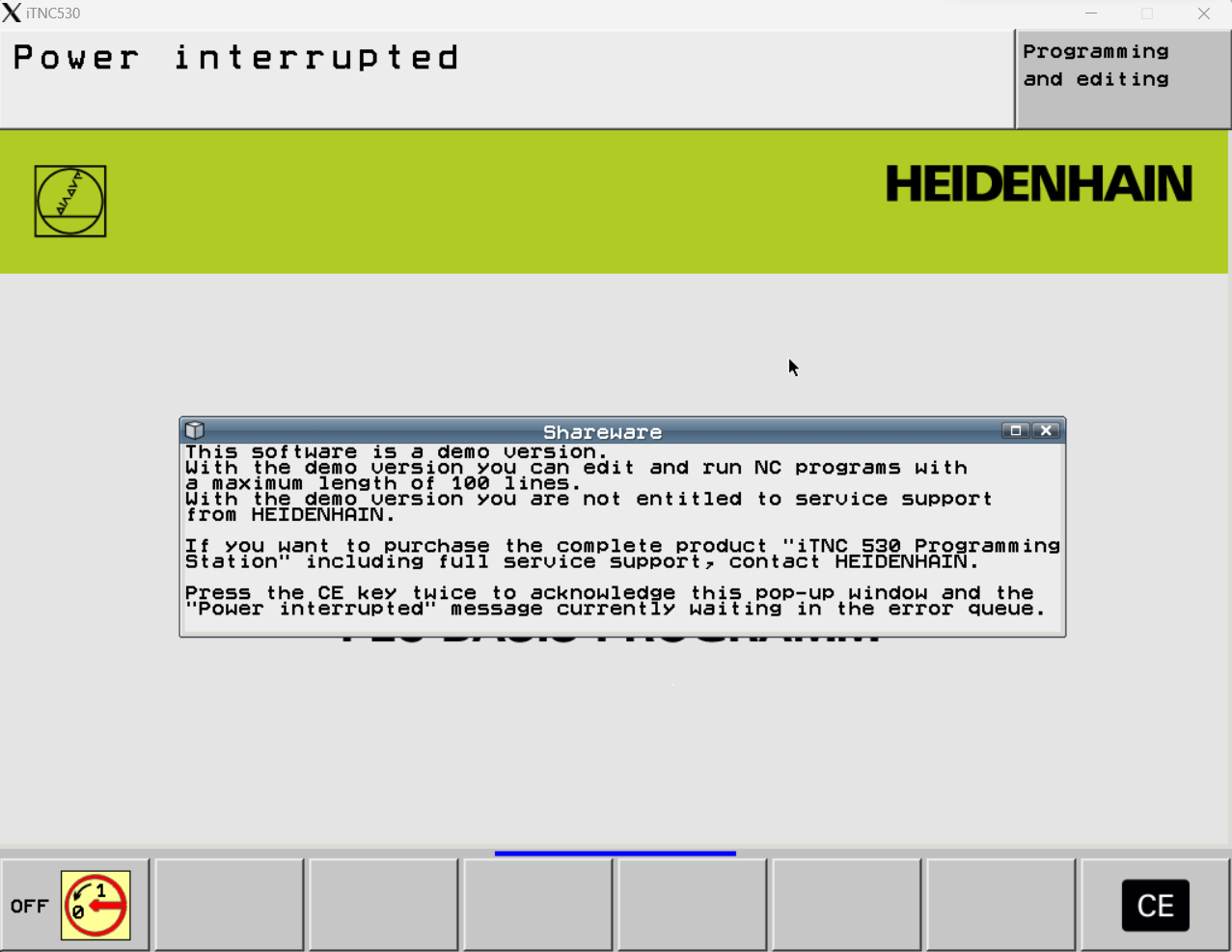
Wait until the Simulator is up. Confirm the with [CE]-button
-
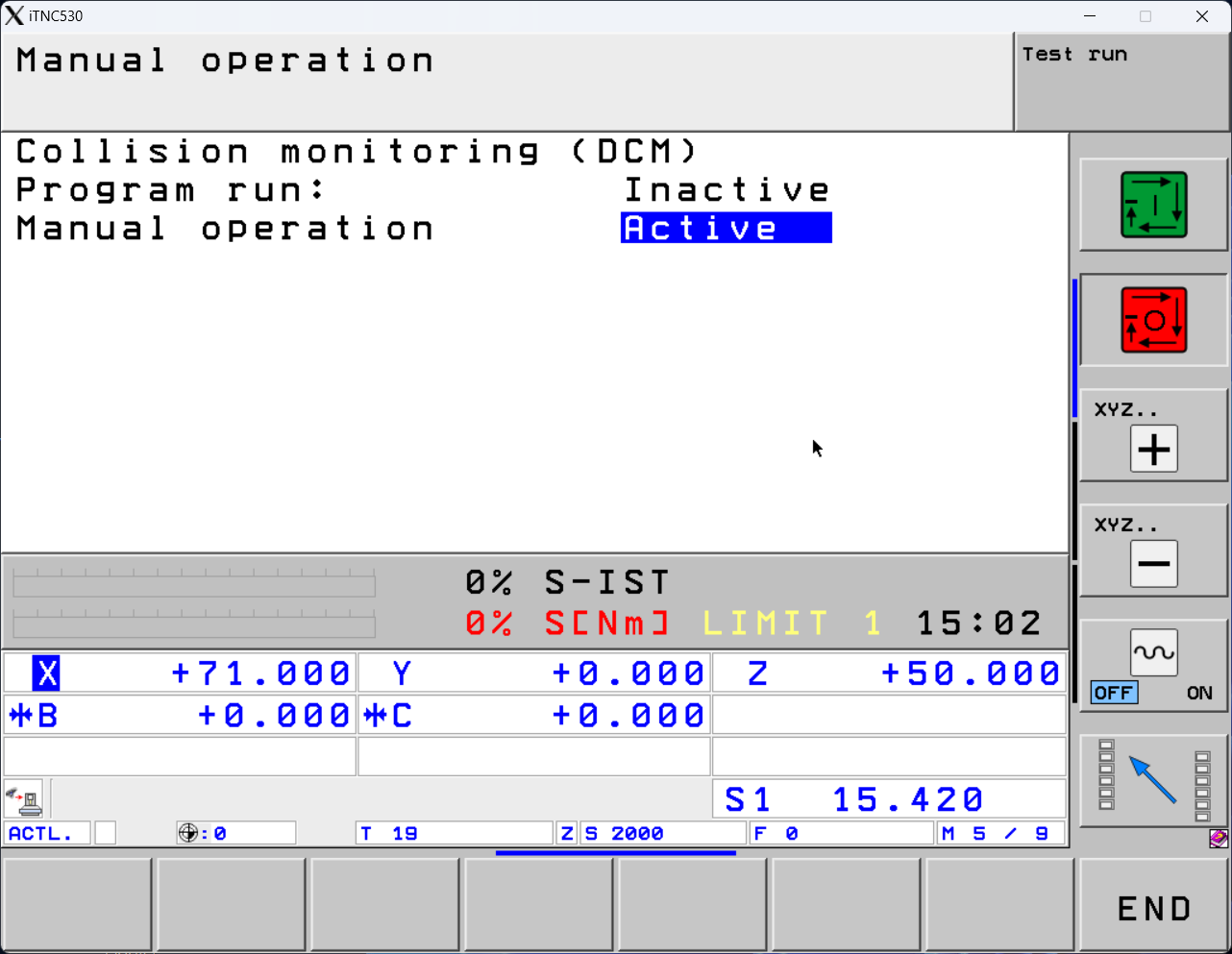
Deactivate the collision check.
- Manual Mode
- Twice [Arrow Right]
- Click on [Collision]
- Set "Program Run" to
Inactive
-
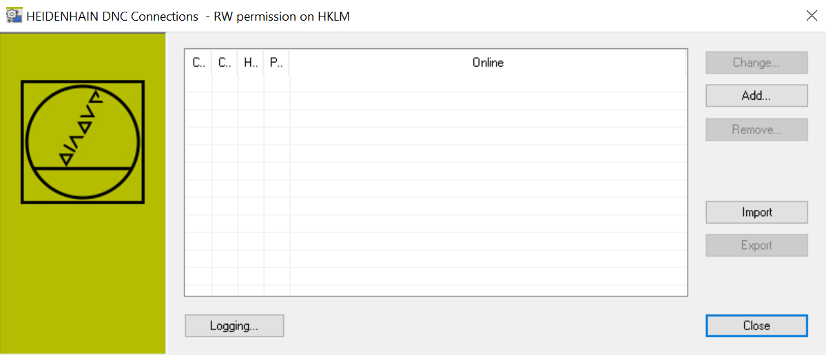
Open the "Create HeidenhainDNC Connection" from Windows Start Menu.
-
Add a new connection. Click [Add]-button
-
Set the name to
ItncSim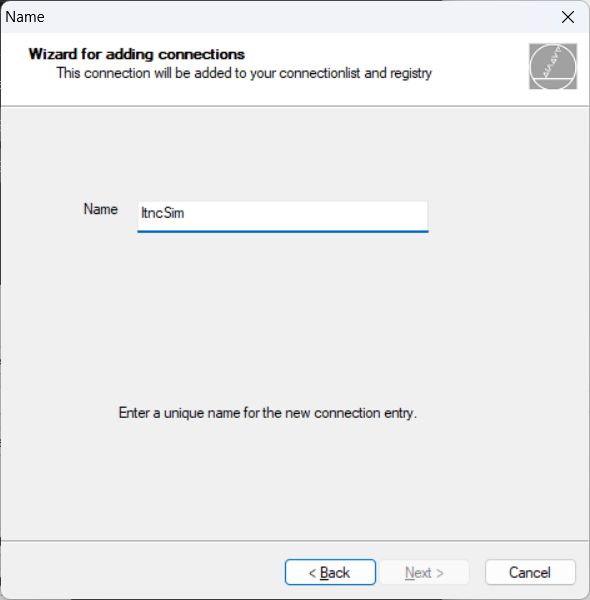
-
Choose the correct NC, e.g. iTNC530
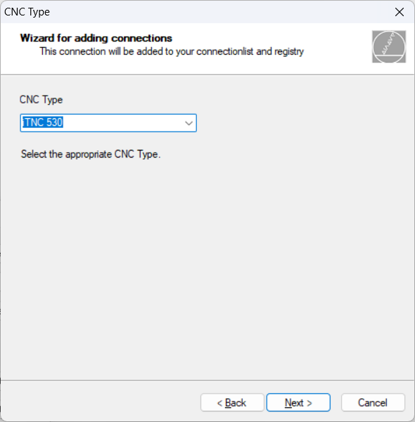
-
Setup the connection parameter. For Heidenhain simulator, use
localhostand port19000.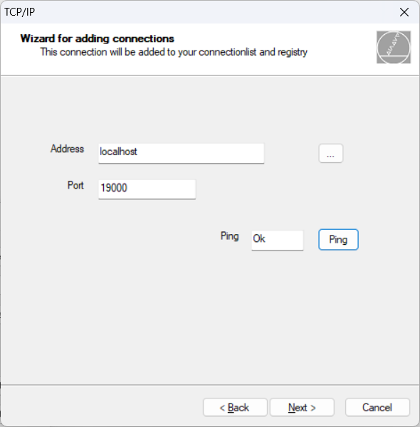
-
The connection shows the state "Online". You are ready to connect to the Heidenhain Controller from the development client.
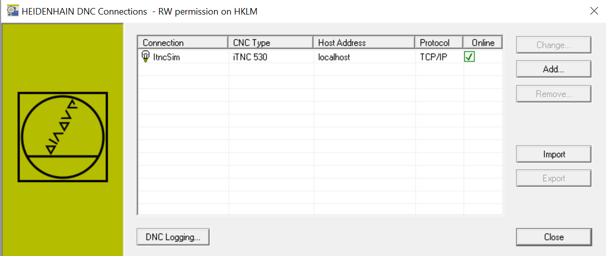
Step 2: Create a Designer Project for Heidenhain
-
Create an IoT project with HumanOS IoT Designer. Check Tutorial 1 Example for details about OPC-UA Bridges.
-
Add a new device template for Heidenhain Controllers.
In this example we use the empty device template.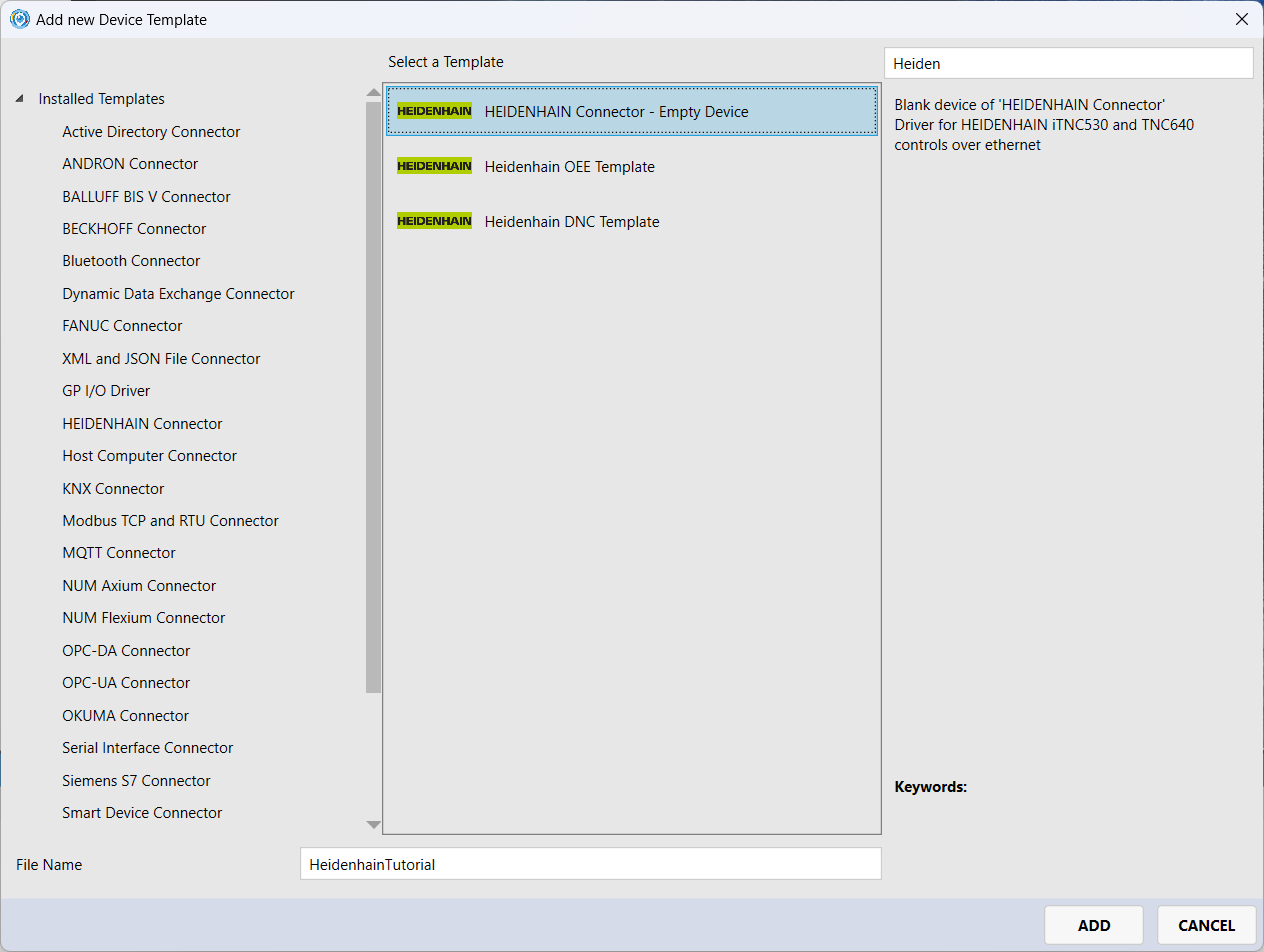
-
Add a group node to the device template with name
Controller.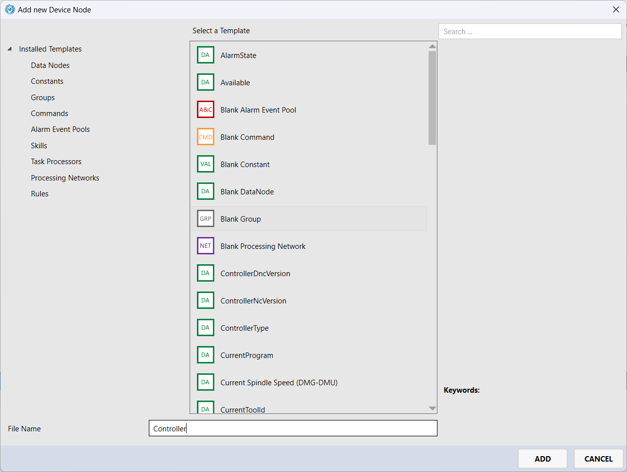
Group nodes help you to structure your device model. For instance, use groups could represent NC paths (channels).
-
Add new data node for
RunningStateto theController-group.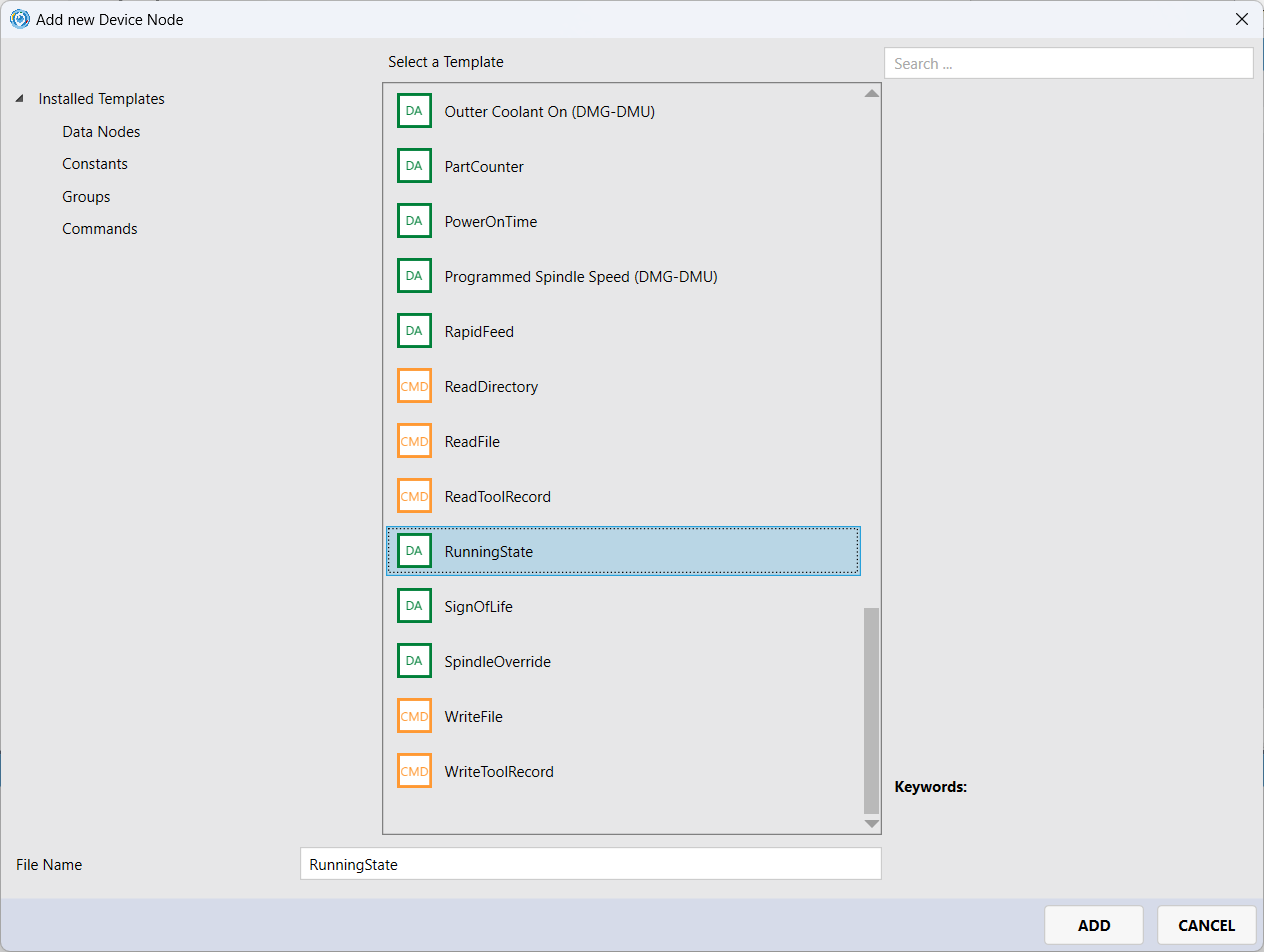
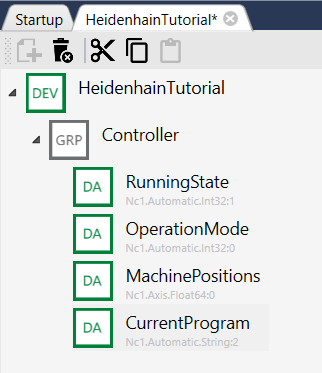
Add other data nodes to the
Controller:OperationModeMachinePositionsCurrentProgram
Your device template looks like this:
-
The details of the data node are shown on the right side of the designer.
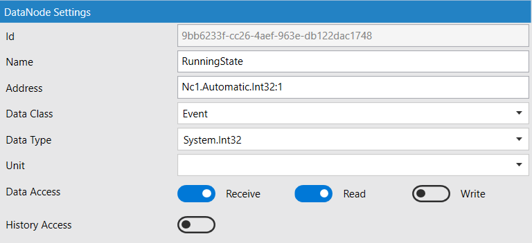
The address field specifies the controller address. It depends on the controller type you selected at the beginning.
Check the manual for Heidenhain controller addresses.
The
Data Typedefines the data type of the data node inside HumanOS NodeSpace.
- Use
System.Doublefor real numbers- Use
System.Int32for integer numbers- Use
System.Stringfor text and character strings
Step 3: Create Heidenhain Device
-
Create a Heidenhain Device within the
default-Target.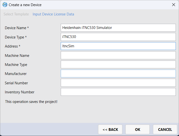
-
Deploy and run HumanOS IoT Gateway
-
Connect with OPC-UA client to the OPC-UA server. Use the connection address
opc.tcp://localhost:4840.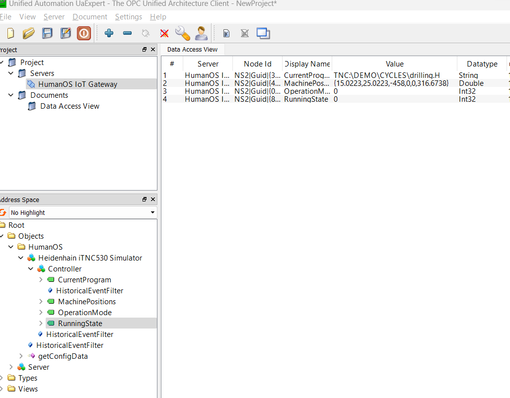
The groups are also mapped to OPC-UA groups.
Extension Step 1: History Mode
-
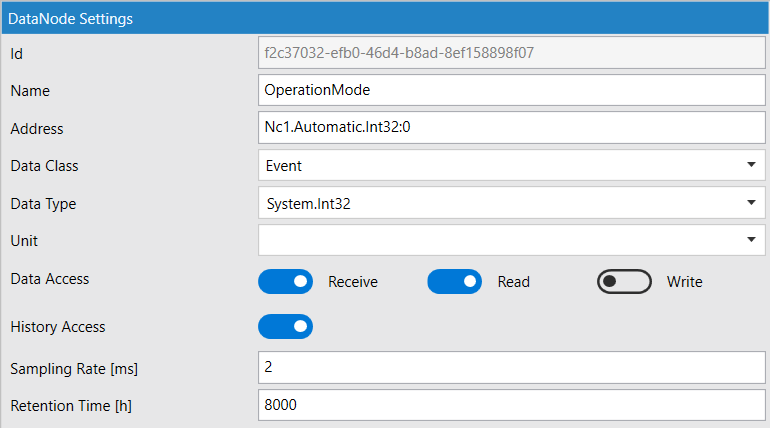
Add the history mode to
OperationMode.-
Sampling Rate: defines the sampling rate for long term history
-
Retention Time: How long are the data stored
Hints
- Reassign the changed device template to your Heidenhain device.
-
History mode could lead to full disks. Therefore, activate the history mode only on selected data nodes and limit the retention time.
-
Deploy and run HumanOS IoT Gateway
-
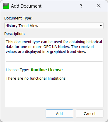
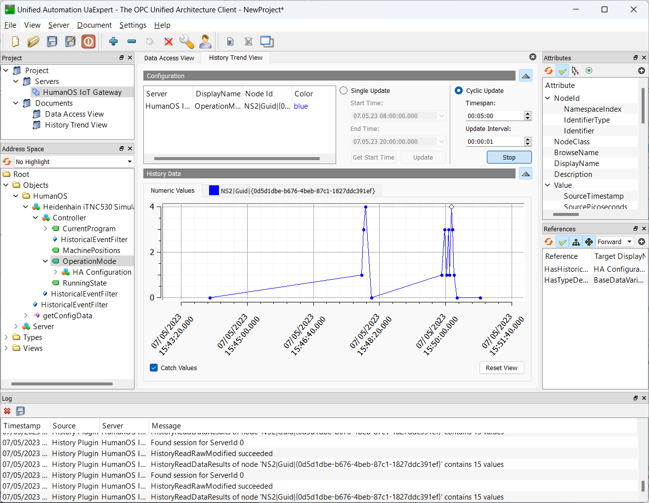
Go to UAExpert and add the history trend view. [Document] - [Add].
-
Drag and Drop the
OperationModeto the "Configuration". -
Select "Cyclic Update" and click [Start]
Extension Step 2: Commands
Commands are used to execute actions on the Heidenhain controller such as reading or writing NC programs.
-
Add the
ReadFilecommand node to theController-group of your device template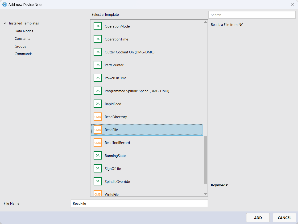
A command defines input and output arguments. In our case, the input argument
Namespecifies the NC program name and path. The output argumentContentcontains the file content after reading.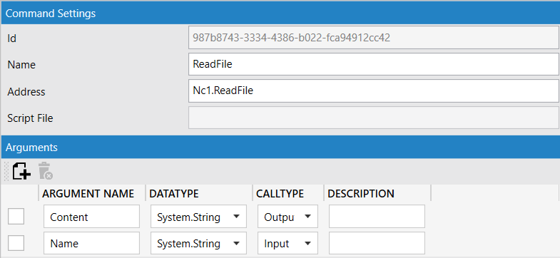
Hints
- Reassign the changed device template to your Heidenhain device.
-
Deploy and run HumanOS IoT Gateway
-
Go to UAExpert and right click on the command
ReadFile. Select [Call] to call the command.
If the OPC-UA command node is not yet visible, you might have to [Rebrowse] the objects first.
Input TNC:\DEMO\CYCLES\cycle28.h as "Name".
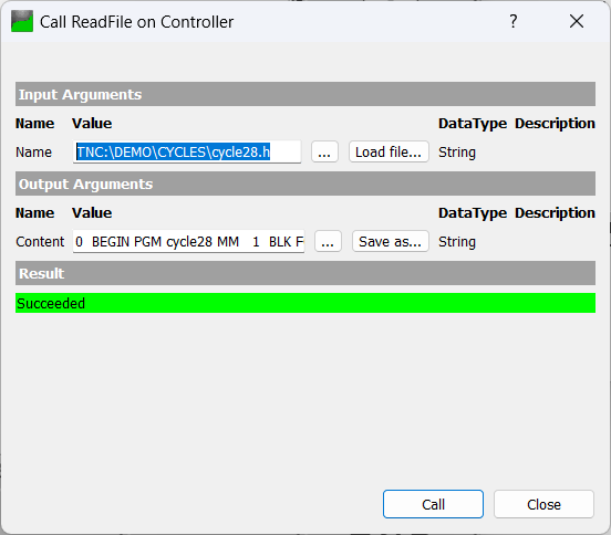
The argument Content contains the NC file:
0  BEGIN PGM cycle28 MM
1  BLK FORM 0.1 Z  X-30  Y-30  Z-15
2  BLK FORM 0.2  X+30  Y+30  Z+0
3  TOOL CALL 19 Z S2000
4  CALL LBL 10
...
36 LBL 99
37 END PGM cycle28 MM
Extension Step 3: Alarm and Event Handling
Alarm and Events are captured by an Alarm Event Pool Node.
-
Select the root node of your device template and add a new device node here. Click [+] button.
-
Select the
MachineAlarmingnode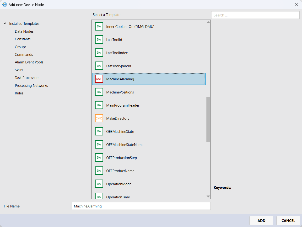
The alarm event pool
MachineAlarmingcontains an alarm task with addressNc1.NcAlarmEvent:0.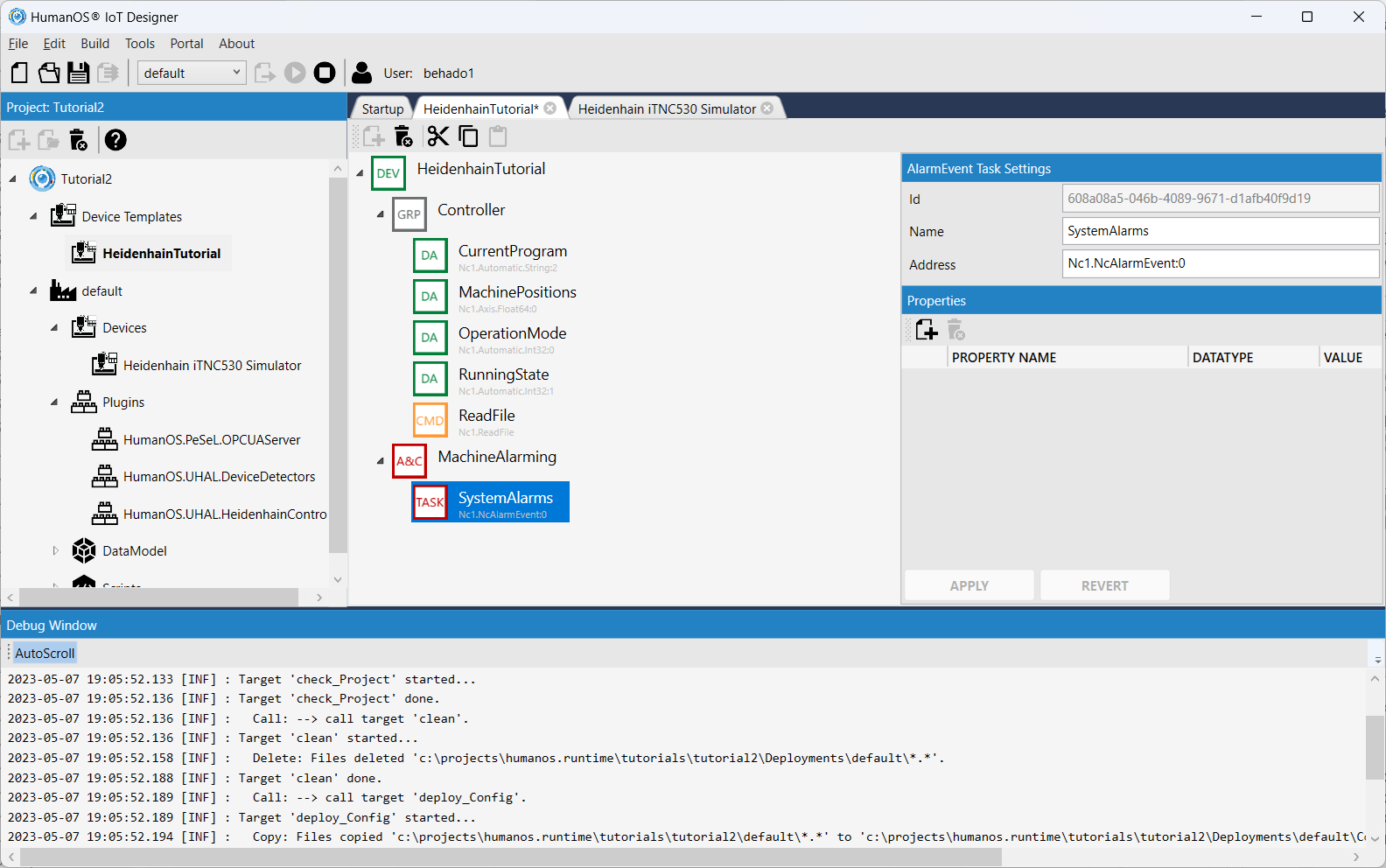
Hints
- Reassign the changed device template to your Heidenhain device.
-
Deploy and run HumanOS IoT Gateway
-
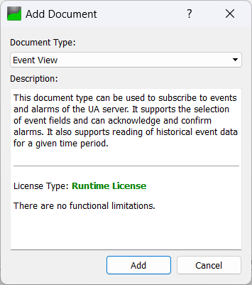
Go to UAExpert and add the history trend view. [Document] - [Add].
-
Drag and Drop the
MachineAlarmingto the "Configuration".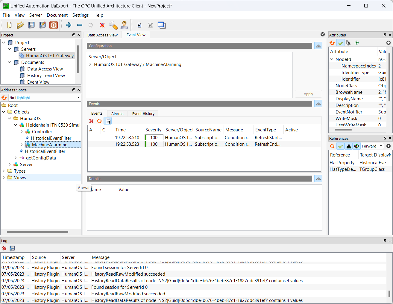
-
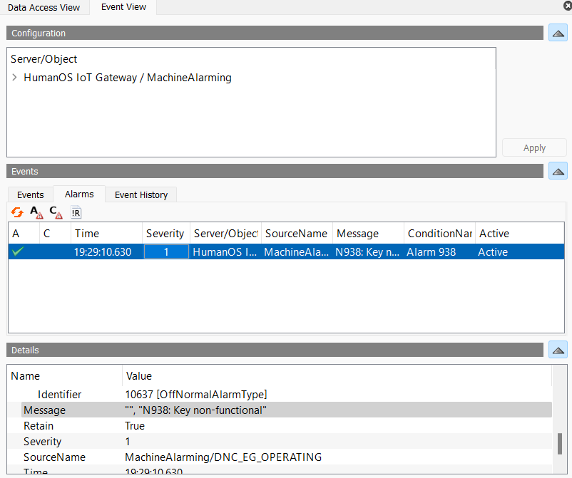
Switch to the Heidenhain Simulator and press any non-functional key, e.g. select Manual mode and then press [GOTO].
-
The alarm appears in the "Event View" of the UAExpert.
Questions
-
What is the main purpose of the device information model?
Answer
The main purpose is to define the access to devices (hardware or software).
-
What are the main node types of the device information model?
Answer
Main node types in device information model are:- Group Node
- Data Node
- Command
- Alarm Event Pool
-
Are there other node types for device information models? Name them.
Answer
Other node types are:- Constant Node
- Processing Network with Data Processor
- Port Matching Rule
-
What information are provided by the Alarm Event Pool for OPC-UA Alarms?
Answer
Following information are passed:- Condition Name
- Message Text
- Source Name
- Time stamp
- Severity of the Event
- Event Id
Further Information
- Manual for Heidenhain Connector
- Manual for OPC-UA Server
- Manual for HumanOS IoT Designer
Source Files
- Source files from Tutorial 2