FANUC Data Access
This chapter outlines all possible native addresses to access memory and data. These addresses must be configured within the device configuration.
Format
A native FANUC address has following format:
{memory base}.{memory type}.{data type}:{address}(.{bit}?)(°{axis}?)`
{bit}and{axis}depend on the memory to read. Check the sections below.
For array reading writing in PCODE and CUSTOM-MV memory, special array addresses are used:
{memory base}.{memory type}.{data type}:{address}[{arraySize}]`
The arraySize argument must be between 1 and 4096.
Memory Base
The CNC control provides different bases for memory:
| Memory Base | Description |
|---|---|
| Global | Global memory base. |
| Nc1...Nc10 | Nc channel memory base. Not that there could exist shared memory between nc channels (path). In this case two different addresses will point to the exact same memory. |
| Pmc1...Pmc3 | Pmc channel memory base. |
| Dcs | Dual check safety memory base. |
Memory Type
Each memory base can have one or several memory types:
| Memory Base | Memory Type | Description |
|---|---|---|
| Global | PCode | Global P-code memory |
| Param | Global parameter memory (axis parameter only) | |
| System | Global CNC Information | |
| Nc1...Nc10 | PCode | Channel specific P-code memory |
| CustomMV | Customer macro variables | |
| Param | Channel specific parameter memory | |
| Diagnosis | Channel specific diagnostic memory | |
| Dynamic | Dynamic memory (process and program states) | |
| Program | Extended program states (see Dynamic for common states) | |
| Modal | Modal memory (commanding state) | |
| Offset | Offset memory (G54, G55, ...) | |
| ToolData | Tool Data from tool table (Radius, Length, Magazine, ...) | |
| ToolOffset | Tool Offset Memory (T1, T2, ...) | |
| ToolLife | Tool Life Data | |
| Axis | Axis state memory (current, load, ...) | |
| Spindle | Spindle memory (current, load, ...) | |
| Timer | Timer memory (power on, operation, cycle, cutting, ...) | |
| System | System Information of the Nc-System | |
| Pmc1...Pmc3, Dsc | Pmc_A | Messages |
| Pmc_C | Counters | |
| Pmc_D | Data tables | |
| Pmc_E | Extra relay | |
| Pmc_F | Input signal to PMC from CNC | |
| Pmc_G | Output signal from PMC to CNC | |
| Pmc_K | Keep relay | |
| Pmc_M | Input signal from another PMC path | |
| Pmc_N | Output signal to another PMC path | |
| Pmc_R | Internal relay | |
| Pmc_T | Timer | |
| Pmc_X | Input signal from PMC to machine | |
| Pmc_Y | Output signal to PMC from machine | |
| Pmc_Z | System relay | |
| System | System information of the PMC |
Data Types
| Address Data Type | Description | Data Type |
|---|---|---|
| Bool | Bit information. 0 = not set; 1 = set | System.Boolean |
| Uint8 | Byte information (unsigned 8bit integer) | System.Byte |
| Uint16 | Word information (unsigned 16bit integer) | System.UInt16 |
| Uint32 | DWord information (unsigned 32bit integer) | System.Uint32 |
| Int32 | Signed integer (32bit) | System.Int32 |
| Float64 | Floating point number (64bit) | System.Double |
| String | String information | System.String |
| Auto | Auto detecting data type (available only for Parameters and Diagnosis) | Auto Detected |
Examples
Nc5.Offset.Float64:1°1 addresses the offset memory of the 5th
Nc-channel.
Dcs.Pmc_R.Uint32:0 addresses the R-memory of the dual check safety
channel.
Global System Configuration
The global system configuration can only be read or monitored. Writing is not possible.
| Address | Description | Data Type |
|---|---|---|
Global.System.String:0 | Control Name | System.String |
Global.System.Int32:1 | Connection status of the control
| System.Int32 |
Global.System.Int32:2 | Sign of life (toggle bit if connection is established) | System.Int32 |
Global.System.Int32:3 | Global number of axis | System.Int32 |
NcChannel System Configuration
The Nc system configuration can only be read or monitored. Writing is not possible.
| Address | Description | Data Type |
|---|---|---|
Nc{n}.System.Int32:0 | Number of axis available in the addressed nc channel | System.Int32 |
Nc{n}.System.String:1 | Names of all axis in a semi-colon separated string (e.g. X;Y;Z;C). | System.String |
Nc{n}.System.Int32:100 | Number of tools available for Tool Offset | System.Int32 |
Nc{n}.System.Int32:1000 | Max number of tool groups (available only when ToolLifeManagement capability) | System.Int32 |
Nc{n}.System.Int32:1001 | Max number of tools (available only when ToolLifeManagement capability) | System.Int32 |
Nc{n}.System.Int32:1002 | Max life time of tool (available only when ToolLifeManagement capability) | System.Int32 |
Nc{n}.System.Int32:1003 | Max number of cutting cycles (available only when ToolLifeManagement capability) | System.Int32 |
Dynamic Memory
The dynamic memory can only be read or monitored. Writing is not possible.
Program Information
| Address | Description | Data Type |
|---|---|---|
Nc{n}.Dynamic.Float64:0 | Main program number | System.Double |
Nc{n}.Dynamic.Float64:1 | Current program number | System.Double |
Nc{n}.Dynamic.Float64:2 | Current sequence number | System.Double |
Nc{n}.Dynamic.Float64:3 | Current spindle speed | System.Double |
Nc{n}.Dynamic.Float64:4 | Current Axis feed | System.Double |
The following data access points require the capability of program management:
The main program name and block number (program line) is supported by:
- Fanuc0i (Model D, F)
- Fanuc30i
- Fanuc31i
- Fanuc32i
- Fanuc35i
- PowerMotion i
| Address | Description | Data Type |
|---|---|---|
Nc{n}.Program.String:0 | Main program name (for 0i_F and 30i-A/B, the program names can be character string). | System.String |
Nc{n}.Program.Int32:1 | Current block number (Program Line Nr.) | System.Int32 |
Nc{n}.Program.String:2 | Current executing block as text | System.String |
Nc{n}.Program.Int32:3 | Current sequence number. | System.Int32 |
Nc{n}.Program.String:10 | Program header of current selected program. The header contains program name/number and the comment. | System.String |
Use
Nc{n}.Program.Int32:3to prevent a well known FANUC issue about sequence number mismatch, when returning from a Macro-B program into Macro-Executer. See issues [Open FANUC Issues].

Operation Information
| Address | Description | Data Type |
|---|---|---|
Nc{n}.Dynamic.Float64:5 | Running state 0 = RESET 1 = STOP 2 = HOLD (program interrupted) 3 = START (program running) 4 = MSTR (during retraction and re-positioning of tool retraction and recovery, and operation of JOG MDI) | System.Double |
Nc{n}.Dynamic.Float64:6 | Alarm state 0 = NO ALARM 1 = ALARM 2 = BATTERY LOW 3 = FAN (NC or Servo Amplifier) 4 = PS Warning 5 = FSSB Warning 6 = LEAKAGE Warning 7 = ENCODER Warning 8 = PMC Alarm | System.Double |
Nc{n}.Dynamic.Float64:7 | Emergency state 0 = none 1 = Emergency 2 = Reset 3 = Wait (FS35i only) | System.Double |
Nc{n}.Dynamic.Float64:8 | Operation mode 0 = MDI (Manual Data Input) 1 = MEM (or automatic mode) 2 = reserved 3 = EDIT (or programming mode) 4 = HANDLE 5 = JOG (or hand mode) 6 = TEACH IN JOG 7 = TEACH IN HANDLE 8 = INC FEED 9 = REFERENCE (referencing the axis) 10 = REMOTE | System.Double |
Nc{n}.Dynamic.Float64:9 | Program restart mode (this might require a Fanuc option) 0 = program not edited 1 = program edited | System.Double |
Axis Positions
There are four axis position types in FANUC
- Machine Positions: machine position coming from the servo motors and axis scales
- Absolute Positions: workpiece related positions towards a workpiece zero point
- Relative Positions: nullable axis positions used to move relative.
- Distance to Go: distance towards the target position (only valid if the nc program is running)
To counter check the values, go to FANUC POS screen:

| Address | Description | Data Type |
|---|---|---|
Nc{n}.Dynamic.Float64:100 | Machine positions | System.Double[] |
Nc{n}.Dynamic.Float64:200 | Absolute positions | System.Double[] |
Nc{n}.Dynamic.Float64:300 | Relative positions | System.Double[] |
Nc{n}.Dynamic.Float64:400 | Distance to go | System.Double[] |
Each one of these memories can be also read by axis number:
| Address | Description | Data Type |
|---|---|---|
Nc{n}.Dynamic.Float64:100°{x} | Machine position of x-th axis | System.Double |
Nc{n}.Dynamic.Float64:200°{x} | Absolute position of x-th axis | System.Double |
Nc{n}.Dynamic.Float64:300°{x} | Relative position of x-th axis | System.Double |
Nc{n}.Dynamic.Float64:400°{x} | Distance to go of x-th axis | System.Double |
Example: Nc1.Dynamic.Float64:100°3 reads the machine position of the
third axis from the Nc channel 1.
Modal Variables
Modal values are commanded by the nc program. They are located on the process screen on FANUC.
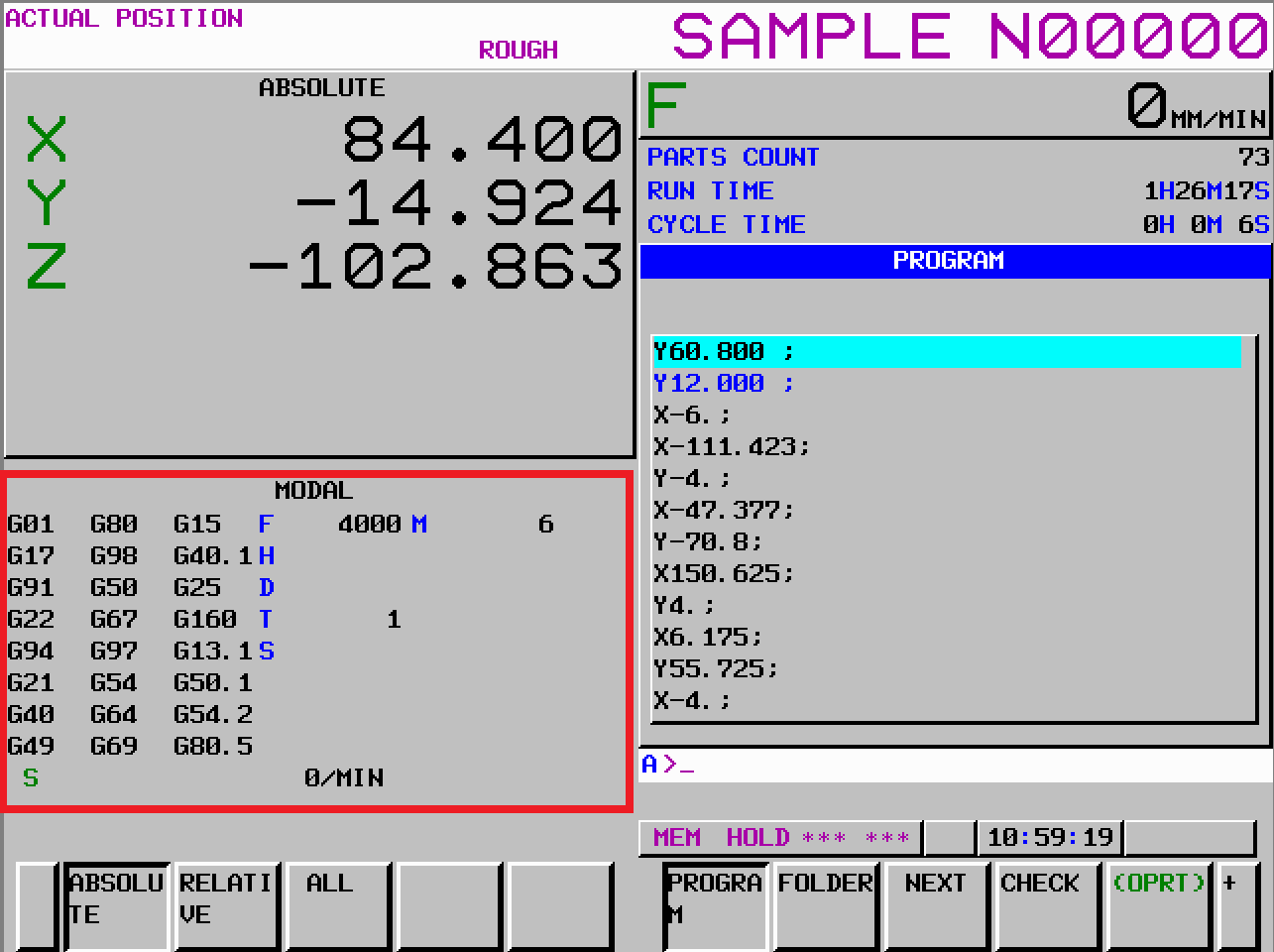
The driver supports following readings:
- G-commands of current and next ISO block
- Modal-parameters (A-Z) of current and next ISO block
- Globally active Modal parameters (as text of double array)
The addresses of the modal commands are in following format:
Nc{x}.Modal.{datatype}:{address}
Modal G-Codes
| Address | Description | Data Type |
|---|---|---|
Nc{n}.Modal.String:0°{x} | Active G-code of the current block. {x} specifies the G-code group. This depends on the FANUC control type (e.g. 30i ranges from 1 to 36). | System.String |
Nc{n}.Modal.String:1°{x} | G-code of the next (preceding) block. | System.String |
Nc{n}.Modal.String:10 | Reading all active G-codes of the current block. The string is “;” separated. | System.String |
Nc{n}.Modal.String:11 | Reading all active G-codes of the next block. The string is “;” separated. | System.String |
G-Codes are grouped. This means only one G-code can be active within a specific group:
Group-Nr {x} | FANUC 15 | FANUC 3xi, 0i-D/E/F M-Series | FANUC 3xi, 0i-D/E/F – T-Series (System A) | FANUC 3xi, 0i-D/E/F – T-Series (System B) | FANUC 3xi, 0i-D/E/F – T-Series (System C) |
|---|---|---|---|---|---|
| 0 | G00, G01, G02, G02.y, G03 G03.y, G06.1, G06.2, G33, G60 | G00, G01, G02, G02.y, G03, G03.y, G06.2, G32.2, G33, G34, G35, G36, G75, G77, G78, G79 | G00, G01, G02, G02.y, G03, G03.y, G06.y, G32, G34, G35, G36, G90, G92, G94 | G00, G01, G02, G02.y, G03, G03.y, G06.y, G33, G34, G35, G36, G77, G78, G79 | G00, G01, G02, G02.y, G03, G03.y, G06.y, G33, G34, G35, G36, G77, G78, G79 |
| 1 | G17, G18, G19 | G17, G71.1, G18, G19 | G96, G97 | G96, G97 | G96, G97 |
| 2 | G90, G91 | G90, G91 | - | G90, G91 | G90, G91 |
| 3 | G22, G23 | G22, G23 | G68, G69 | G68, G69 | G68, G69 |
| 4 | G93, G94, G95 | G93, G93.1, G93.2, G94, G95 | G93, G93.3, G98, G99 | G93, G93.3, G98, G99 | G93, G93.3, G98, G99 |
| 5 | G20, G21 | G20 (G70), G21 (G71) | G20, G21 | G20, G21 | G20, G21 |
| 6 | G40, G41, G41.2, G41.3, G42, G42.2 | G40, G41, G41.y, G42, G42.y | G40, G41, G41.y, G42, G42.y | G40, G41, G41.y, G42, G42.y | G40, G41, G41.y, G42, G42.y |
| 7 | G43, G43.1, G44, G49 | G43, G43.y, G44, G44.1 | G25, G26 | G25, G26 | G25, G26 |
| 8 | G73. G74, G76, G80, G81, G82, G83, G84, G84.2, G84.3. G85, G86, G87, G88, G89 | G73. G74, G76, G80, G81, G81.2, G82, G83, G84, G84.2, G84.3. G85, G86, G87, G88, G89 | G22, G23 | G22, G23 | G22, G23 |
| 9 | G98, G99 | G98, G99 | G80, G81, G82, G83, G83.1, G83.5, G84, G84.1, G84.2, G85, G86, G87, G87.5, G87.6, G88, G89 | G80, G81, G82, G83, G83.1, G83.5, G84, G84.1, G84.2, G85, G86, G87, G87.5, G87.6, G88, G89 | G80, G81, G82, G83, G83.1, G83.5, G84, G84.1, G84.2, G85, G86, G87, G87.5, G87.6, G88, G89 |
| 10 | G50, G51 | G50, G51 | - | G98, G99 | G98, G99 |
| 11 | G66, G66.1, G67 | G66, G66.1, G67 | G66, G66.1, G67 | G66, G66.1, G67 | G66, G66.1, G67 |
| 12 | G96, G97 | G96, G97 | - | - | - |
| 13 | G54, G54.1, G54.2, G55, G56, G57, G58, G59 | G54, G54.1, G54.2, G55, G56, G57, G58, G59 | G54, G54.1, G54.2, G55, G56, G57, G58, G59 | G54, G54.1, G54.2, G55, G56, G57, G58, G59 | G54, G54.1, G54.2, G55, G56, G57, G58, G59 |
| 14 | G61, G62, G63, G64 | G61, G62, G63, G64 | G61, G62, G63, G64 | G61, G62, G63, G64 | G61, G62, G63, G64 |
| 15 | G68, G69 | G68, G68.2, G68.3, G68.4, G69 | G17, G17.1, G18, G19 | G17, G17.1, G18, G19 | G17, G17.1, G18, G19 |
| 16 | G15, G16 | G15, G16 | G68.y, G69.1 | G68.y, G69.1 | G68.y, G69.1 |
| 17 | G50.1, G50.2 | G40.1 (G150), G41.1 (G151), G42.1 (G152) | - | G50, G51 | G50, G51 |
| 18 | G40.1, G41.1, G42.1 | G25, G26 | G40.1, G41.1, G42.1 | G40.1, G41.1, G42.1 | G40.1, G41.1, G42.1 |
| 19 | - | G160, G161 | G50.2 (G250), G51.2 (G251) | G50.2 (G250), G51.2 (G251) | G50.2 (G250), G51.2 (G251) |
| 20 | - | G12.1 (G112), G13.1 (G113) | G12.1 (G112), G13.1 (G113) | G12.1 (G112), G13.1 (G113) | G12.1 (G112), G13.1 (G113) |
| 21 | - | G50.1, G51.1 | G50.1, G51.1 | G50.1, G51.1 | G50.1, G51.1 |
| 22 | - | G54.2 | G43, G43.y (G44.7), G44, G44.1, G49 (G49.1) | G43, G43.y (G44.7), G44, G44.1, G49 (G49.1) | G43, G43.y (G44.7), G44, G44.1, G49 (G49.1) |
| 23 | - | G80.5, G81.5 | G15, G16 | G15, G16 | G15, G16 |
| 24 | G25, G26 | - | G05.5. G05.6 | G05.5. G05.6 | G05.5. G05.6 |
| 25 | G12.1, G13.1 | - | G54.4 | G54.4 | G54.4 |
| 26 | - | G44.9, G49.9 | G80.5, G81.5 | G80.5, G81.5 | G80.5, G81.5 |
| 27 | G80.5, G81.5 | - | G80.4, G81.4 | G80.4, G81.4 | G80.4, G81.4 |
| 28 | - | - | G08.8, G08.9 | G08.8, G08.9 | G08.8, G08.9 |
| 29 | - | G54.3 | G05.7, G05.8 | G05.7, G05.8 | G05.7, G05.8 |
| 30 | - | G50.2, G51.2 | G10.3, G10.4, G10.5 | G10.3, G10.4, G10.5 | G10.3, G10.4, G10.5 |
| 31 | - | G05.5, G05.6 | - | - | - |
| 32 | - | G54.4 | - | - | - |
| 33 | - | G80.4, G81.4 | - | - | - |
| 34 | - | G12. G13 | - | - | - |
| 35 | - | G08.8, G08.9 | - | - | - |
| 36 | - | G05.7, G05.8 | - | - | - |
Modal Parameters
The modal parameters are all variables of an ISO program except G-commands.
- Positions, like
X,YandZvalues - Feed, parameter
F - Tool id, parameter
T - ...
These parameters can be read as single value (like “programmed feed”, or
as double array returning all parameter at once, or as text like
X102.00 F910 M3.
| Address | Description | Data Type |
|---|---|---|
Nc{n}.Modal.Float64:2°{x} | Other commanded modal variables of the current block. {x} specifies the command id (letter). See table below. | System.Double |
Nc{n}.Modal.Float64:3°{x} | Other commanded modal variables of the next block. | System.Double |
Nc{n}.Modal.Float64:4°{x} | Global modal variables. {x} specifies the command id (letter). See table below. | System.Double |
Nc{n}.Modal.Float64:12 | Reading all commanded modal variables of the current block and returns an array. | System.Double[] |
Nc{n}.Modal.Float64:13 | Reading all commanded modal variables of the next block and returns an array. | System.Double[] |
Nc{n}.Modal.Float64:14 | Reading all globally active modal variables and returns an array. | System.Double[] |
Nc{n}.Modal.String:22 | Reading all commanded modal variables of the current block. The data is returned as a formatted string. | System.String |
Nc{n}.Modal.String:23 | Reading all commanded modal variables of the next block. The data is returned as a formatted string. | System.String |
Nc{n}.Modal.String:24 | Reading all globally active modal variables. The data is returned as a formatted string. | System.String |
Example: Nc1.Modal.String:22 returns X-12.281 Z90 F0.6
The following table show the mapping of {x} to the command id (letter):
| x | Command | x | Command | x | Command | x | Command |
|---|---|---|---|---|---|---|---|
| 0 | A | 8 | I | 16 | Q | 24 | Y |
| 1 | B | 9 | J | 17 | R | 25 | Z |
| 2 | C | 10 | K | 18 | S | 26 | M (2nd) |
| 3 | D | 11 | L | 19 | T | 27 | M (3rd) |
| 4 | E | 12 | M (1st) | 20 | U | 28 | M (4th) |
| 5 | F | 13 | N | 21 | V | 29 | M (5th) |
| 6 | G | 14 | O | 22 | W | ||
| 7 | H | 15 | P | 23 | X |
Tool Offset Memory
Tool offset memory is used to correct a single tool (or tool edge).
To counter check the values, go to the SET-screen on FANUC and click on
[OFFSET]:
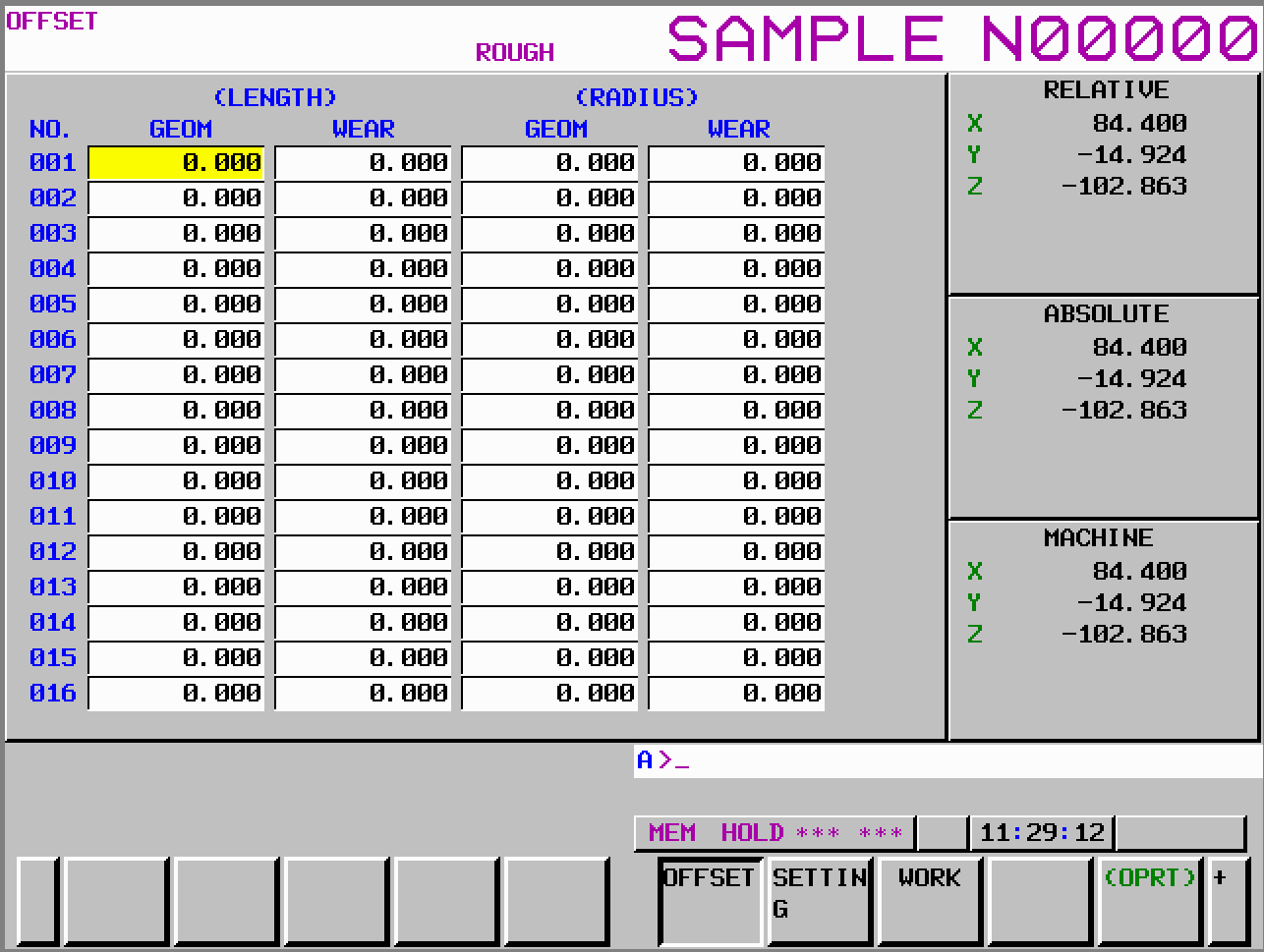
The tool offset memory is readable and writeable.
Note that the axis numbers are not the id’s from the real axis, but the geometric axis id. The correlation between real axis id and geometric axis id is set in FANUC parameters (see FANUC Manual).
| Address | Description | Data Type |
|---|---|---|
Nc{n}.ToolOffset.Float64:{x}°1 | X-axis geometry offset | System.Double |
Nc{n}.ToolOffset.Float64:{x}°2 | Y-axis geometry offset | System.Double |
Nc{n}.ToolOffset.Float64:{x}°3 | Z-axis geometry offset or tool length offset (tool length geometry) | System.Double |
Nc{n}.ToolOffset.Float64:{x}°4 | Nose radius geometry offset (Cutter radius geometry) | System.Double |
Nc{n}.ToolOffset.Float64:{x}°5 | Direction of imaginary tool nose | System.Double |
Nc{n}.ToolOffset.Float64:{x}°6 | X-axis wear offset | System.Double |
Nc{n}.ToolOffset.Float64:{x}°7 | Y-axis wear offset | System.Double |
Nc{n}.ToolOffset.Float64:{x}°8 | Z-axis wear offset or tool wear offset (tool length wear) | System.Double |
Nc{n}.ToolOffset.Float64:{x}°9 | Cutter radius wear | System.Double |
{x} specifies the tool number (typically 1...32, but there exist options
to range up to 2000).
Reading memory using addresses without °{x} returns the whole structure
as a double-array:
| Address | Description | Data Type |
|---|---|---|
Nc{n}.ToolOffset.Float64:{x} | Tool offset data | System.Double[] |
Workpiece Offset Memory
The workpiece offset memory is used to offset (correct) the absolute positions in relation to the zero point on the workpiece.
FANUC has different memories that can be switched in nc program:
G54-G59: standard workpiece offsetsG54.x: extended workpiece offsets
To counter check the values, go to the SET-screen on FANUC and click on
[WORK]:
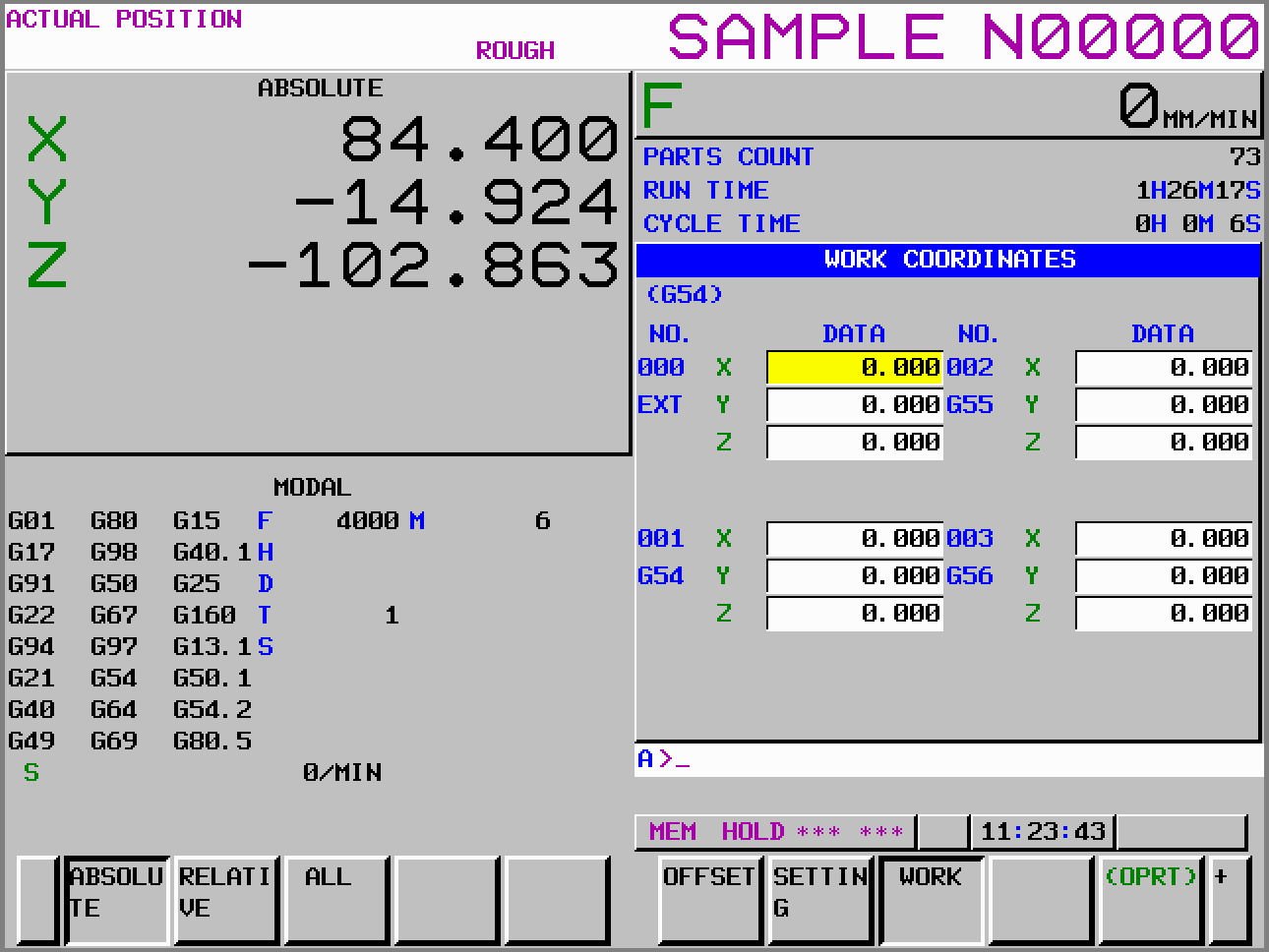
The work offset memory is readable and writable. To access the memory,
axis number must be given: {x}.
Single Value
Axis values are automatically converted to metric or inches respectively.
| Address | Description | Data Type |
|---|---|---|
Nc{n}.Offset.Float64:0°{x} | Reads or writes the external work zero offset value | System.Double |
Nc{n}.Offset.Float64:1°{x} | Reads or writes the work zero offset value of G54 | System.Double |
Nc{n}.Offset.Float64:2°{x} | Reads or writes the work zero offset value of G55 | System.Double |
Nc{n}.Offset.Float64:3°{x} | Reads or writes the work zero offset value of G56 | System.Double |
Nc{n}.Offset.Float64:4°{x} | Reads or writes the work zero offset value of G57 | System.Double |
Nc{n}.Offset.Float64:5°{x} | Reads or writes the work zero offset value of G58 | System.Double |
Nc{n}.Offset.Float64:6°{x} | Reads or writes the work zero offset value of G59 | System.Double |
Depending on FANUC control options, following extended work zero offsets can be accessed:
Series 15/15i and 0i-D:
| Address | Description | Data Type |
|---|---|---|
Nc{n}.Offset.Float64:{y}°{x} | Reads or writes the work zero offset value of G54.1 P{y-6} with {y} ranging from 7 to 54 | System.Double |
M Series 16/18/21, 16i/18i/21i, 0i-A/B/C and
M/T Series 0i-F and 30i:
| Address | Description | Data Type |
|---|---|---|
Nc{n}.Offset.Float64:{y}°{x} | Reads or writes the work zero offset value of G54.1 P{y-6} with {y} ranging from 7 to 306 | System.Double |
Arrays
For arrays, only reading is supported.
| Address | Description | Data Type |
|---|---|---|
Nc{n}.Offset.Float64:0 | Reads the external work zero offset value | System.Double[] |
Nc{n}.Offset.Float64:1 | Reads the work zero offset value of G54 | System.Double[] |
Nc{n}.Offset.Float64:2 | Reads the work zero offset value of G55 | System.Double[] |
Nc{n}.Offset.Float64:3 | Reads the work zero offset value of G56 | System.Double[] |
Nc{n}.Offset.Float64:4 | Reads the work zero offset value of G57 | System.Double[] |
Nc{n}.Offset.Float64:5 | Reads the work zero offset value of G58 | System.Double[] |
Nc{n}.Offset.Float64:6 | Reads the work zero offset value of G59 | System.Double[] |
Depending on your control, following extended work zero offsets can be read:
Series 15/15i and 0i-D:
| Address | Description | Data Type |
|---|---|---|
Nc{n}.Offset.Float64:{y}° | Reads or writes the work zero offset value of G54.1 P{y-6} with {y} ranging from 7 to 54 | System.Double[] |
M Series 16/18/21, 16i/18i/21i, 0i-A/B/C and
M/T Series 0i-F and 30i:
| Address | Description | Data Type |
|---|---|---|
Nc{n}.Offset.Float64:{y}° | Reads or writes the work zero offset value of G54.1 P{y-6} with {y} ranging from 7 to 306 | System.Double[] |
Axis Status and Diagnostics
The axis status and diagnostic memory can only be read or monitored. Writing is not possible.
| Address | Description | Data Type |
|---|---|---|
Nc{n}.Axis.Float64:0 | Reads the servo meter of all axis | System.Double[] |
Nc{n}.Axis.Float64:1 | Reads the servo current of all axis | System.Double[] |
Nc{n}.Axis.Float64:2 | Reads the servo loop gain of all axis | System.Double[] |
Each one of these memories can be also read by axis number:
| Address | Description | Data Type |
|---|---|---|
Nc{n}.Axis.Float64:0°{x} | Reads the servo meter of the x-th axis | System.Double |
Nc{n}.Axis.Float64:1°{x} | Reads the servo current of the x-th axis | System.Double |
Nc{n}.Axis.Float64:2°{x} | Reads the servo loop gain of the x-th axis | System.Double |
Other axis data is accessible using the FANUC Trace.
Spindle Status
Spindle status must be read aside from the axis status.
| Address | Description | Data Type |
|---|---|---|
Nc{n}.Spindle.Float64:0 | Reads the load meter of all spindles | System.Double[] |
Nc{n}.Spindle.Float64:1 | Reads the speeds of all spindles | System.Double[] |
Each one of these memories can be also read by spindle number:
| Address | Description | Data Type |
|---|---|---|
Nc{n}.Spindle.Float64:0°{x} | Reads the load meter of the x-th spindle | System.Double |
Nc{n}.Spindle.Float64:1°{x} | Reads the speed of the x-th spindle | System.Double |
Other spindle data is accessible using the FANUC Trace.
Timer
FANUC provides different timers:
| Address | Description | Data Type |
|---|---|---|
Nc{n}.Timer.Float64:0 | Reads the power on timer [min] | System.Double |
Nc{n}.Timer.Float64:1 | Reads the operation timer [min] | System.Double |
Nc{n}.Timer.Float64:2 | Reads the cutting timer [min] | System.Double |
Nc{n}.Timer.Float64:3 | Reads the cycle timer [min] | System.Double |
Nc{n}.Timer.String:10 | Reads the system date and time | System.String |
FANUC also provides two timers on the NC side: a millisecond timer
#3001 and an hour timer #3002.
Use the CustomMV address to access these timers:
Nc{n}.CustomMV.Float64:3001for millisecond timer (read/write)Nc{n}.CustomMV.Float64:3002for hour timer (read/write)
Customer Macro Variables
The addresses of customer macro variables are in the following format:
Nc{n}.CustomMV.Float64:{address}
The {address} must be in the range of the CNC settings.
| Address | Description | Data Type |
|---|---|---|
Nc{n}.CustomMV.Float64:{1...33} | Reads or writes local variables belonging to the macro program being executed. ONLY READING! | System.Double |
Nc{n}.CustomMV.Float64:{100...999} | Reads or writes common variables. The range depends on the CNC settings and options | System.Double |
Nc{n}.CustomMV.Float64:{1000...} | Reads or writes system variables. ONLY READING! | System.Double |
Nc{n}.CustomMV.Float64:{98000...98499} | Reads or writes common variables. The range depends on the CNC settings and options | System.Double |
Example:
Nc1.CustomMV.Float64:20reads the local variable#20on the first NC path.Nc2.CustomMV.Float64:900reads the common variable#900on the second NC path.
Arrays
The customer macro variables can also be read or written as an array. The array size can be freely chosen between 1 to 4096.
Nc{n}.CustomMV.Float64:{address}[{arraySize}]
Example:
Nc1.CustomMV.Float64:500[32]reads 32 common variables starting from#500on the first NC path.
Variable Ranges
Depending on the FANUC control type and their options, different variable ranges are valid:
| CNC Type | Option | Ranges |
|---|---|---|
| Series 15 M/T | 0 | 100,..,149 500,..,549 |
| 1 | 100,..,199 500,..,599 | |
| 2 | 100,..,199 500,..,699 | |
| 3 | 100,..,199 500,..,999 | |
| Series 15 TT | 0 | 100,..,149 500,..,524 |
| 1 | 100,..,149 500,..,549 | |
| 2 | 100,..,149 500,..,599 | |
| 3 | 100,..,149 500,..,749 | |
| Series 15i | 3 | 100,..,199 500,..,999 |
| 4 | 100,..,199 200,..,999 | |
| Series 16/18/21, 16i/18i/21i, 0i-A/B/C | 0 | 100,..,149 500,..,531 |
| 1 | 100,..,199 500,..,999 | |
| 2 | 100,..,199 500,..,599 | |
| Series 16i/18i-W | 0 | 100,..,149 500,..,531 |
| 1 | 100,..,314 500,..,699 | |
| 2 | 100,..,149 500,..,699 | |
| 3 | 100,..,314 500,..,531 | |
| 4 | 100,..,149 500,..,999 | |
| 5 | 100,..,314 500,..,999 | |
| Power Mate i | 0 | 100,..,149 500,..,531 |
| 1 | 100,..,199 500,..,999 | |
| 2 | 100,..,199 500,..,699 | |
| Series 30i/31i/32i, 0i-D/F, PMi-A | 0 | 100,..,149 500,..,549 |
| 1 | 100,..,199 500,..,999 | |
| 2 | 100,..,149 200,..,499 500,..,549 | |
| 3 | 100,..,499 500,..,999 | |
| 4 | 100,..,199 500,..,999 98000,..,98499 | |
| 5 | 100,..,499 500,..,999 98000,..,98499 |
Reading arrays only works inside one range.
P-Code Variables
The addresses of the P-code variables are in the following format:
Nc{n}.PCode.Float64:{address}
The {address} must be in the range of the CNC settings.
| Address | Description | Data Type |
|---|---|---|
Nc{n}.PCode.Float64:{10000...89999} | Reads or writes a P-code address | System.Double |
Nc{n}.PCode.Float64:{< 10000} | Reads or writes a System P-code address of “conversation” macro | System.Double |
Example:
Nc1.PCode.Float64:10000reads the P-code variable#10000on the first NC path.
Arrays
The P-code variables can also be read or written as an array. The array size can be freely chosen between 1 to 4096.
Nc{n}.PCode.Float64:{address}[{arraySize}]
Example:
Nc1.PCode.Float64:10100[32]reads 32 common variables starting from#10100on the first NC path.
PMC Variables
The addresses of the PMC variables are in the following format:
{PmcType}.{MemoryType}.{DataType}:{address}.{bit?}
Following pmc types are supported:
| PMC Type | Description |
|---|---|
Pmc1 | Main PMC (first PMC channel) |
Pmc2 | Second PMC channel |
Pmc3 | Third PMC channel |
Dcs | Dual check safety channel |
Following memory types are supported:
| Memory Type | Description |
|---|---|
Pmc_A | Messages |
Pmc_C | Counters |
Pmc_D | Data tables |
Pmc_E | Extra relay |
Pmc_F | Input signal to PMC from CNC |
Pmc_G | Output signal from PMC to CNC |
Pmc_K | Keep relay |
Pmc_M | Input signal from another PMC path |
Pmc_N | Output signal to another PMC path |
Pmc_R | Internal relay |
Pmc_T | Timer |
Pmc_X | Input signal from PMC to machine |
Pmc_Y | Output signal to PMC from machine |
Pmc_Z | System relay |
The pmc type
Dcssupports only memory typesPmc_RandPmc_D.
The base data type of all pmc memory is Uint8. All other data types
are derived accordingly:
| Data Type | Description | Example |
|---|---|---|
| Bool | Reading or writing a bit information. Bit information require the {bit} number (0 to 7) after the memory address. | Pmc1.Pmc_D.Bool:100.1 |
| Uint8 | Reading or writing a byte information | Pmc2.Pmc_A.Uint8:9 |
| Uint16 | Reading or writing a word information | Dcs.Pmc_R.Uint16:192 |
| Uint32 | Reading or writing a dword information | Pmc1.Pmc_X.Uint32:100 |
PMC Information
The addresses of the PMC information variables are in the following format:
Pmc1.System.String:{address}
Following addresses are supported:
| Address | Description |
|---|---|
| Pmc1.System.String:0 | Machine tool builder name |
| Pmc1.System.String:1 | Machine tool name |
| Pmc1.System.String:2 | NC & PMC type name |
| Pmc1.System.String:3 | PMC program number |
| Pmc1.System.String:4 | Edition number |
| Pmc1.System.String:5 | Program drawing number |
| Pmc1.System.String:6 | Creation date of the program |
| Pmc1.System.String:7 | Author of the program |
| Pmc1.System.String:8 | Company or person who wrote the ROM |
| Pmc1.System.String:9 | Remarks |
Parameter
The addresses of the parameter variables are in the following format:
Nc{n}.Param.{datatype}:{address}{.bit?}{°axis?}
Global{n}.Param.{datatype}:{address}{.bit?}{�°axis?}
The {bit} or {axis} part must be added depending on the parameter from FANUC. The {bit} can only be added for Bool data type.
| Data Type | Description | Example |
|---|---|---|
| Bool | Reading or writing a bit information. Bit information require the {bit} number 0 to 7 after the memory address. | Nc1.Param.Bool:100.1 or Nc5.Param.Bool:3201.1°5 |
| Uint8 | Reading or writing a byte information. | Nc1.Param.Uint8:9 |
| Uint16 | Reading or writing a word information. | Nc6.Param.Uint16:192 |
| Uint32 | Reading or writing a dword information. | Nc2.Param.Int32:5241 |
| Int32 | Reading or writing an integer information. | Nc2.Param.Int32:5241 |
| Float64 | Reading or writing a float value information. | Nc3.Param.Float64:9281°1 |
| Auto | Reading or writing a value information. The data type is automatically detected from the parameter info on the CNC. | Nc3.Param.Auto:981°1 |
Use global addresses to access axis parameter from multiple NC path, e.g.
Global.Param.Uint8:981°1. To know how many axis are globally available, useGlobal.System.Int32:3. This feature is only supported for 0i-D/F, 30i-A/B, 31i-A/B and Power Motion-i controls.
For Axis parameters, it's possible to read all axis at once. The data is returned as an array. The data type of the DataNode must be an array type, like
System.Double[]. In this case{axis}is left out, e.g.Global.Param.Uint8:981. Important: This can be used only to read axis parameters. Writing axis parameter requires exact addresses including{axis}.
Example:
Reading the channel (path) assignment of each axis. This must be read globally to receive information from all channels (paths).
The parameter is byte based and it returns a byte-array because Global.Param.Uint8:981 contains no {axis} address.
{
  "Id": "5ab17bbc-3759-4eb0-bcc2-02600046d62c",
  "Name": "AxisInChannel",
  "Address": "Global.Param.Uint8:981",
  "DataType": "System.Byte[]",
  "Unit": "",
  "Access": {
    "Read": true,
    "Receive": true
  },
  "Properties": []
}
Diagnosis
The addresses of the diagnosis variables are in the following format:
Nc{n}.Diagnosis.{datatype}:{address}{.bit?}{°axis?}
The {bit} or {axis} part must be added depending on the diagnosis item
you want to read. Note that {bit} can only be added for Bool data type.
| Data Type | Description | Example |
|---|---|---|
| Bool | Reading a bit information. Bit information require the {bit} number 0 to 7 after the memory address. | Nc1.Diagnosis.Bool:100.1 or Nc5.Diagnosis.Bool:3201.1°5 |
| Uint8 | Reading a byte information. | Nc1.Diagnosis.Uint8:9 |
| Uint16 | Reading a word information. | Nc6.Diagnosis.Uint16:192 |
| Uint32 | Reading a dword information. | Nc2.Diagnosis.Int32:5241 |
| Int32 | Reading an integer information. | Nc2.Diagnosis.Int32:5241 |
| Float64 | Reading a float value information. | Nc3.Diagnosis.Float64:9281°1 |
| Auto | Reading a value information. The data type is automatically detected from the diagnosis info on the CNC. | Nc3.Diagnosis.Auto:981°1 |
Tool Management Data
The following addresses can be used to read tool data out of the FANUC tool table.
Nc{n}.ToolData.Float64:{ToolId}°{FieldNr}
This table shows the different fields to be read from to tool table:
| Address | Name | FANUC FieldName |
|---|---|---|
Nc{n}.ToolData.Float64:{ToolId}°1 | tool number(T) | T_code |
Nc{n}.ToolData.Float64:{ToolId}°2 | tool life counter | life_count |
Nc{n}.ToolData.Float64:{ToolId}°3 | maximum of tool life | max_life |
Nc{n}.ToolData.Float64:{ToolId}°4 | rest of tool life | rest_life |
Nc{n}.ToolData.Float64:{ToolId}°5 | state of tool life | life_stat |
Nc{n}.ToolData.Float64:{ToolId}°6 | customizing bit | cust_bits |
Nc{n}.ToolData.Float64:{ToolId}°7 | tool info. | tool_info |
Nc{n}.ToolData.Float64:{ToolId}°8 | tool length compensation number (H) | H_code |
Nc{n}.ToolData.Float64:{ToolId}°9 | cutter compensation number (D) | D_code |
Nc{n}.ToolData.Float64:{ToolId}°10 | spindle speed (S) | spindle_speed |
Nc{n}.ToolData.Float64:{ToolId}°11 | feed rate(F) | feedrate |
Nc{n}.ToolData.Float64:{ToolId}°12 | magazine number | magazine |
Nc{n}.ToolData.Float64:{ToolId}°13 | pot number | pot |
Nc{n}.ToolData.Float64:{ToolId}°14 | tool geometric compensation number(G) | G_code |
Nc{n}.ToolData.Float64:{ToolId}°15 | tool wear compensation number(W) | W_code |
Nc{n}.ToolData.Float64:{ToolId}°16 | tool geometric number | gno |
Nc{n}.ToolData.Float64:{ToolId}°17 | edge group number(only 0i-F, 30i/31i/32i) | grp |
Nc{n}.ToolData.Float64:{ToolId}°18 | edge number(only 0i-F, 30i/31i/32i) | edge |
Nc{n}.ToolData.Float64:{ToolId}°19 | origin magazine number(only 0i-F, 30i/31i/32i) | org_magazine |
Nc{n}.ToolData.Float64:{ToolId}°20 | origin pot number(only 0i-F, 30i/31i/32i) | org_pot |
Tool Life Management Memory
The tool life management is a special management memory of tool wear, life and sister tools.
The Tool Life Management (TLM) option of FANUC must be also enabled on the FANUC controls. Check the FANUC manuals for description of the TLM.
Addressing Tool Life Memory
The tool life management (TLM) is realized as a double array. Therefore, the address room (32bit address) is split into two sections: the high-word represents the tool group address, the low-word represents the tool address.
The address must by given in HEX format.
Example: the address 0x00100009 is split into 0x0010 and 0x0009
(hex) or 16 and 9 in decimal.
Status Information (Address 0x00000000)
| Address | Description | Data Type |
|---|---|---|
Nc{n}.ToolLife.Int32:0x00000000 | Reads the current status of the TLM | System.Int32[] |
Nc{n}.ToolLife.Int32:0x00000000°1 | Reads the number of tool group currently selected | System.Int32 |
Nc{n}.ToolLife.Int32:0x00000000°2 | Reads the number of tool group currently in use | System.Int32 |
Nc{n}.ToolLife.Int32:0x00000000°3 | Reads the number of tool group to be used next | System.Int32 |
Nc{n}.ToolLife.Int32:0x00000000°4 | Reads the number of tool optional group currently selected | System.Int32 |
Nc{n}.ToolLife.Int32:0x00000000°5 | Reads the number of tool optional group currently in use | System.Int32 |
Nc{n}.ToolLife.Int32:0x00000000°6 | Reads the number of tool optional group to be used next | System.Int32 |
Tool Group Information
The high-word of the address specifies the Group Id, written as {group}. The low-word is always zero.
The address 0x000A0000 points to the information of 10th
group.
| Address | Description | Data Type |
|---|---|---|
Nc{n}.ToolLife.Int32:0x{group}{0000} | Reads the current status of the group {group} | System.Int32[] |
Nc{n}.ToolLife.Int32:0x{group}{0000}°1 | Reads the number of used tools | System.Int32 |
Nc{n}.ToolLife.Int32:0x{group}{0000}°2 | Reads the number of free tools | System.Int32 |
Nc{n}.ToolLife.Int32:0x{group}{0000}°3 | Reads the selected tool in order | System.Int32 |
Nc{n}.ToolLife.Int32:0x{group}{0000}°4 | Reads the tool life counter type | System.Int32 |
Nc{n}.ToolLife.Int32:0x{group}{0000}°5 | Reads or writes the tool life counter | System.Int32 |
Nc{n}.ToolLife.Int32:0x{group}{0000}°6 | Reads the rest of tool life counter* | System.Int32 |
Nc{n}.ToolLife.Int32:0x{group}{0000}°7 | Reads the rest signal state* | System.Int32 |
Nc{n}.ToolLife.Int32:0x{group}{0000}°8 | Reads the optional tool group\ | System.Int32 |
Nc{n}.ToolLife.Int32:0x{group}{0000}°9 | Reads the tool life (in total) | System.Int32 |
Note: These items are only available for tool life management B function is set. Parameter
6805.4(Tool life management B)
Tool Life Information
The high-word of the address specifies the Group Id, written as {group}. The low-word is addresses the tool within that group.
The address 0x00100002 points to the 2nd tool information of
16th group
| Address | Description | Data Type |
|---|---|---|
Nc{n}.ToolLife.Int32:0x{group}{tool} | Reads the current status of the tool {tool} | System.Int32[] |
Nc{n}.ToolLife.Int32:0x{group}{tool}°1 | Reads the tool identification number | System.Int32 |
Nc{n}.ToolLife.Int32:0x{group}{tool}°1 | Reads the status of the tool
| System.Int32 |
Nc{n}.ToolLife.Int32:0x{group}{tool}°3 | Reads the tool length compensation number (Zero in T-series) | System.Int32 |
Nc{n}.ToolLife.Int32:0x{group}{tool}°4 | Reads the cutter radius compensation number (Zero in T-series) | System.Int32 |
Trace Addresses
The following addresses are only accessible with SDK using the TFanucDataTracer class.
Axis Trace
| Address | Description | Data Type |
|---|---|---|
Nc{n}.Axis.Float64:100°{x} | Reads position feedback (POSF) of axis {x} | System.Double[] |
Nc{n}.Axis.Float64:101°{x} | Reads position error (ERR) of axis {x} | System.Double[] |
Nc{n}.Axis.Float64:102°{x} | Reads velocity command (VCMD) of axis {x} | System.Double[] |
Nc{n}.Axis.Float64:103°{x} | Reads torque command (TCMD) of axis {x} | System.Double[] |
Nc{n}.Axis.Float64:104°{x} | Reads speed feedback signal (SPEED) of axis {x} | System.Double[] |
Nc{n}.Axis.Float64:105°{x} | Reads estimated disturbance torque (DTRQ) of axis {x} | System.Double[] |
Nc{n}.Axis.Float64:107°{x} | Reads OVC simulation data (OVCLV) of axis {x} | System.Double[] |
Nc{n}.Axis.Float64:108°{x} | Reads effective current (IEFF) of axis {x} | System.Double[] |
Nc{n}.Axis.Float64:123°{x} | Reads reactive current (ID) of axis {x} | System.Double[] |
Nc{n}.Axis.Float64:124°{x} | Reads active current (IQ) of axis {x} | System.Double[] |
Nc{n}.Axis.Float64:125°{x} | Reads motor winding temperature (MTTMP) of axis {x} | System.Double[] |
Nc{n}.Axis.Float64:126°{x} | Reads pulse coder temperature (PCTMP) of axis {x} | System.Double[] |
Nc{n}.Axis.Float64:131°{x} | Reads vibration frequency (FREQ) of axis {x} | System.Double[] |
Nc{n}.Axis.Float64:132°{x} | Reads vibration torque command (FRTCM) of axis {x} | System.Double[] |
Spindle Trace
| Address | Description | Data Type |
|---|---|---|
Nc{n}.Axis.Float64:101°{x} | Reads motor speed (SPEED) of spindle {x} | System.Double[] |
Nc{n}.Axis.Float64:102°{x} | Reads torque command (TCMD) of spindle {x} | System.Double[] |
Nc{n}.Axis.Float64:103°{x} | Reads motor speed command (VCMD) of spindle {x} | System.Double[] |
Nc{n}.Axis.Float64:106°{x} | Reads spindle load torque (DTRQ) of spindle {x} | System.Double[] |
Nc{n}.Axis.Float64:108°{x} | Reads motor winding temperature (MTTMP) of spindle {x} | System.Double[] |
Nc{n}.Axis.Float64:110°{x} | Reads frequency of disturbance torque(FREQ) of spindle {x} | System.Double[] |
Nc{n}.Axis.Float64:111°{x} | Reads gain data(GAIN) of spindle {x} | System.Double[] |
Nc{n}.Axis.Float64:112°{x} | Reads torque command 2(TCMD2) of spindle {x} | System.Double[] |
Nc{n}.Axis.Float64:117°{x} | Reads velocity error (VERR) of spindle {x} | System.Double[] |
Nc{n}.Axis.Float64:118°{x} | Reads spindle speed (SPSPD) of spindle {x} | System.Double[] |
Often used Variables
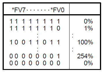
Feedrate
The feed rates are exchanged between PMC and NC modules. Therefore the variables are located in the PMC-G memory.
| Address | Description | Data Type |
|---|---|---|
Pmc{n}.Pmc_G.Uint8:12 | Reads the current federate override 1 | System.Int32 |
Pmc{n}.Pmc_G.Uint8:13 | Reads the current federate override 2 (Option) | System.Int32 |
Note that the value is encoded:
The programmed feed of the nc path is stored in the modal parameters.
| Address | Description | Data Type |
|---|---|---|
Nc{n}.Modal.Float64:2°5 | Reads the programmed feed (parameter F) | System.Double |
Nc{n}.Dynamic.Float64:4 | Reads the current axis feed | System.Double |
Workpiece Counter
| Address | Description | Data Type |
|---|---|---|
Nc{n}.Param.Uint32:6711 | Number of machined parts | System.Uint32 |
Nc{n}.Param.Uint32:6712 | Total number of machined parts | System.Uint32 |
Depending on the application, NC programs may run endlessly. In these cases the workpiece counter is not increased automatically.
Following Macro System-Variables can be used:
| Variable | Description |
|---|---|
#3901 | Number of machined parts (machined) |
#3902 | Number of parts required |
Modify your NC-Programs in the following way to increase the part counter:
%
O0010 (ENDLESS)
N10
…
#3901 = #3901 + 1 (INCREASE THE COUNTER)
GOTO10
M30
%
Operation Hours
| Address | Description | Data Type |
|---|---|---|
Nc{n}.Param.Uint32:6750 | Integrated value of power on period in minutes | System.UInt32 |
Nc{n}.Param.Uint32:6751 | Operation time in milliseconds (integrated value of time during automatic operation)* | System.UInt32 |
Nc{n}.Param.Uint32:6752 | Operation time in minutes (integrated value of time during automatic operation)* | System.UInt32 |
Nc{n}.Param.Uint32:6753 | Integrated value of cutting time in milliseconds ** | System.UInt32 |
Nc{n}.Param.Uint32:6754 | Integrated value of cutting time in minutes** | System.UInt32 |
Nc{n}.Param.Uint32:6757 | Cutting time of current run in milliseconds ** | System.UInt32 |
Nc{n}.Param.Uint32:6758 | Cutting time of current run in minutes** | System.UInt32 |
*Total time of operation in [min] = #6752 + #6752 / 60000
** Total cutting time [min] = #6754 + #6754 / 60000
Customized Cycle Time
If the process is realized in an endless nc program, the system cycle time cannot be used.
Following example shows, how to use the millisecond time of the nc
#3001 as a customized cycle time. Note, that you use some kind of
read-ahead-stop M50 to prevent FANUC interpreter to pre read lines
ahead.
%
O0200(MAT 837121)
N10
M50
#3001=0(RESET TIMER)
…
M50
#501=#3001/1000(CYCLE TIME SEC)
GOTO10
M30
%