Introduction
Modbus TCP Control Driver is part of the HumanOS® Runtime. It allows to integrate Modbus TCP devices into the smart industrial machining platform.
This document explicitly describes the Driver. For common description on HumanOS® Runtime, Software Design and device information files, see the "Operation Manual".
Modbus TCP Control Driver
The Modbus TCP Control Driver is a ubiquitous hardware abstraction (UHAL) plugin of HumanOS® Runtime. The plugin is an event-based plugin. The performance depends on the following factors:
- Location of the HumanOS® Runtime Host (from a network view, place as near as possible to the PLC)
- Number of TCP connections available for the Driver to the device
The connections are established on TCP Port defined by the device address setting, so make sure it is open.
This manual helps system engineers to configure and maintain the Modbus TCP Control Driver and HumanOS® Runtime setups.
One device connection can be managed by the driver.
Connection Information
The Modbus TCP Driver needs an Endpoint address (IP), TCP port and a slave Id.
Supported Devices
Following devices are supported:
- All devices that support modbus TCP/IP communication
Driver Configuration
The driver configuration file is named "settings.json" located in <install directory>\config\HumanOS.UHAL.ModbusTcpControl\.
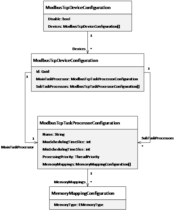
Figure 1: Configuration model of the ModBus TCP Plugin
Modbus TCP Device Configuration
The element "ModbusTcpDeviceConfiguration" contains all settings that belong to a Modbus Tcp device. There are two types:
- The default configuration applies to all detected Modbus Tcp devices. The element does NOT contain any identification attribute
- Specific configuration applies only to the device that matches the identification attribute.
| Attribute | Description | Data Type |
|---|---|---|
| Id | Device Id | System.Guid |
Task Processors
It contains the task processors (threads) that handle different facets of the Modbus Tcp control driver, like:
- Memory management (command, read, write and monitoring)
- Alarm and event management
At least one processor is needed. It is called "MainTaskProcessor".
| Attribute | Description | Data Type |
|---|---|---|
| Name | Name of the processor (used for log information) | System.String |
| ProcessingPriority | Thread priority. Possible values are: (Normal (default); BelowNormal; AboveNormal; Highest) | System.Threading. ThreadPriority |
| MaxSchedulingTimeSlice | [Optional] Maximum time slice in milliseconds between two Modbus Tcp operations. Default value is 5ms. | System.Int32 |
| MinSchedulingTimeSlice | [Optional] Minimum time slice in milliseconds between two Modbus Tcp operations. Default value is 1ms. | System.Int32 |
The attributes MaxSchedulingTimeSlice and MinSchedulingTimeSlice allow to reduce the processor load for low-power computers. For regular industrial computers use the default settings for max. performance.
Additionally, different sub task processors can be added (named "SubTaskProcessor"). They allow to manage specific facets of the driver in parallel. Several tasks can be predefined and added to the processors.
Memory Mapping
By default, all memory types are mapped to the main task processor. The memory mapping helps to assign the memory type address to another task processor. This helps to distribute the data processing load to different tasks (threads).
Note that if two task processors use the same memory mapping, the workload is split among these processors.
| Attribute | Description | Data Type |
|---|---|---|
| MemoryType | Memory type of the assigned memory. This setting is optional. If empty, all memory types of the memory base are handled by this processor. | EMemoryType |
Following example assigns the "Alarming" MemoryType to the SubTaskProcessor "Alarming":^
{
  "Name": "AlarmEventProcessor",
  "ProcessingPriority": "Normal",
  "MaxSchedulingTimeSlice": 500,
  "MinSchedulingTimeSlice": 100,
  "MemoryMappings": [
    {
      "MemoryType": "Alarming"
    }
  ]
}
Use the processing priority setting carefully!! Impropriate settings may cause high processor loads and could slow down the overall system performance. We recommend that only one of the processors is set to “Highest”.
Alarm and Event Handling
It is recommended to use a separate task processor for alarming and OEM message mapping.
For alarm configurations, see chapter 4.
Example
Following example shows a configuration of two task processors. The "MainTaskProcessor" handles the commanding, reading, writing and monitoring or all memories within the device. The "AlarmEventProcessor" manages the alarm and events.
{
  "Disabled": false,
  "Devices": [
    {
      "MainTaskProcessor": {
        "Name": "Main TaskProcessor",
        "ProcessingPriority": "Highest",
        "MaxSchedulingTimeSlice": 5,
        "MinSchedulingTimeSlice": 1
      },
      "SubTaskProcessors": [
        {
          "Name": "AlarmEventProcessor",
          "ProcessingPriority": "Normal",
          "MemoryMappings": [
            {
              "MemoryType": "Alarming"
            }
          ]
        }
      ]
    }
  ]
}
Device Information File
The Modbus TCP Device information file contains:
- Groups
- Data Access Points
- Alarm Source
Detailed reference for device information files, see the HumanOS® Operational Manual chapter "Device Information File".
Connection Address
The Address for Modbus TCP Control must be provided like following:
| Name | Description | Example |
|---|---|---|
| Address | IP address and Port | 10.256.35.32:502:1 |
This information is contained by the device configuration.
Property MemorySizes
To ensure a correct functioning, each Element which is accessed on the device (e.g. Register, Input, Output, etc...) must be declared with its maximum accessible size. Since the driver always fetches more than the declared data, it is crucial to set its register limits. This will then be added to the Device Properties. The default block size fetched is 120 + 3 (256 bytes) for 16-bit registers and 1992 + 8 for 1-bit registers (250 bytes).
Example for OpenPLC:
{
  "Name": "MemorySizes",
  "Value": "InputBit:*=799\nCoilBit:*=799\nInputRegister:*=1023\nHoldingRegister:*=8191"
}
Property PageSizes
Not all devices support transfers of 256 bytes at once. If the device only supports 64 bytes, then the below example fits the need:
Example for Device:
{
  "Name": "PageSizes",
  "Value": "InputBit=248\nCoilBit=248\nInputRegister=29\nHoldingRegister=29"
}
In the example above, the settings are in bits for InputBit and CoilBit, and in words for InputRegister and HoldingRegister. Insert this as Device Property, if nothing is declared the values listed in chapter 2.6 are used.
Modbus TCP Memory Locations and Sizes
This data is device specific. The example shown below is valid for OpenPLC!
As mentioned, these offsets and data sizes are device dependent. For example, on an OpenPLC this looks like this:
| Memory Type | Range | Example | Modbus memory offset |
|---|---|---|---|
| InputBit | I0.0 – I99.7 | InputBit.Boolean:1.0 = I1.0 | 0 |
| CoilBit | Q0.0 – Q99.7 | CoilBit.Boolean:2.2 = Q2.2 | 0 |
| InputRegister | IW0 - IW1023 | InputRegister.UInt16:10 = IW10 | 0 |
| HoldingRegister | MW1024 - MW2047 / DW2048- DW4095 / LW4096 - LW8191 | HoldingRegister. UInt16:1024 = MW0; HoldingRegister. UInt8:1025 = MW1; HoldingRegister.Float32:2048 = DW1; HoldingRegister. UInt32:2050 = DW2; HoldingRegister.Float64:2048 = LW1; HoldingRegister. UInt64:2052 = LW2 | 1024(16-bit) /2048(32-bit) /4096(64-bit) |
As seen the value which is stored in the holding registers or input registers is always 16 bits long, despite the data type.
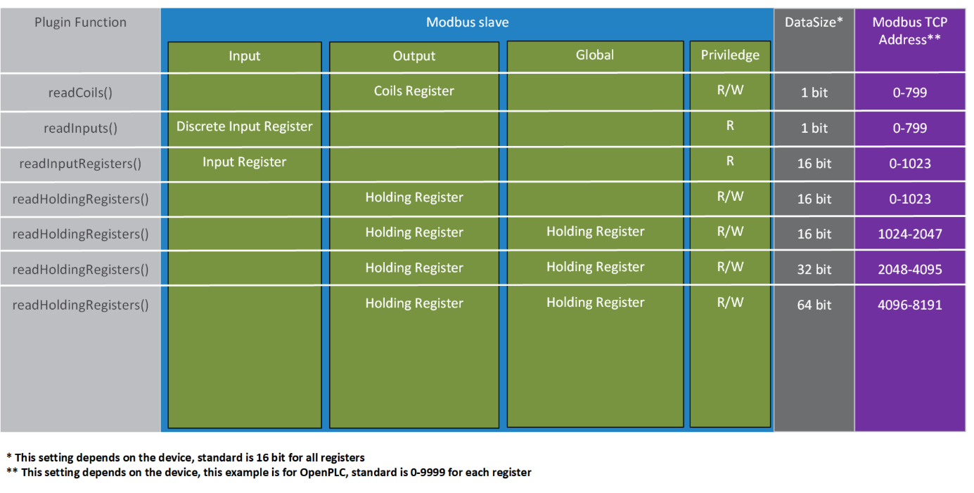
Registers explained
As seen in the chapters before, modbus has different registers. From a data type view, there are only two different registers: a bitwise and a 16-bit register.
The input- and CoilBitregister can only be addressed bitwise.
The input- and holding register are 16-bit registers, which means they can hold all data types supported. For data types bigger than 16-bit like double words (UInt32), two or more registers must be combined.
In newer modbus devices, these ranges are declared (see image in previous chapter).
If a double word value is needed the definition on the different platforms looks like this (openplc example):
Definition programming software plc: %DW0
Definition HumanOS® Address: Holdingregister.UInt32:2048
The next address would look like this:
Definition programming software plc: %DW1
Definition HumanOS® Address: Holdingregister.UInt32:2050
Keep in mind that the counting of the HumanOS® address is dependent on the absolute offset of the modbus device, so as shown, if two combined registers are used, the offset is raised by 2, for 64-bit combined values by 4.
For values lower than 16-bit e.g. byte (UInt8) the used memory space is still 16-bit, the offset is raised by one.
Calculating the maximum Memory Size
If the maximum memory size of the target is unknown or it is not necessary to fetch that much data, the maximum memory size per target can be calculated like following:
Search for the address with the highest offset per target. Calculate the maximum target range with help of the data type.
Example Address: HoldingRegister.Float32:14

Example
{
  "Id": "7ea0317f-8f83-4e3e-a822-7498de01240f",
  "Name": "OpenPLC",
  "DriverId": "4a06a655-36c2-4430-ae27-aaaa4a431395",
  "Address": "address=10.196.24.11;port=502;slaveId=1",
  "Properties": [
    {
      "Name": "MemorySizes",
      "Value": "InputBit:*=799\nCoilBit:*=799\nInputRegister:*=1023\nHoldingRegister:*=8191"
    }
  ],
  "DataNodes": [
    {
      "Id": "e7c89c04-ff87-4951-95fa-6be81a29442d",
      "Name": "input00",
      "DataClass": "Event",
      "DataType": "System.Boolean",
      "Address": "InputBit.Boolean:0.0",
      "Access": {
        "Read": true,
        "Receive": true
      },
      "HistoryMode": {
        "Retention": 100,
        "SamplingRate": 2000
      }
    },
    {
      "Id": "14AE9CB7-6155-46EB-9A8D-8C859A75E7C8",
      "Name": "output00",
      "DataClass": "Event",
      "DataType": "System.Boolean",
      "Address": "CoilBit.Boolean:0.0",
      "Access": {
        "Read": true,
        "Receive": true
      },
      "HistoryMode": {
        "Retention": 100,
        "SamplingRate": 2000
      }
    },
    {
      "Id": "99CBDAB9-D5DC-470A-85F4-71EBB177C0AF",
      "Name": "inputreg",
      "DataClass": "Event",
      "DataType": "System.UInt16",
      "Address": "InputRegister.UInt16:0",
      "Access": {
        "Read": true,
        "Receive": true
      },
      "HistoryMode": {
        "Retention": 100,
        "SamplingRate": 2000
      }
    },
    {
      "Id": "04E7DEDE-2D32-4CD7-9573-FF895BF7E550",
      "Name": "qw1",
      "DataClass": "Event",
      "DataType": "System.UInt32",
      "Address": "HoldingRegister.UInt32:1",
      "Access": {
        "Read": true,
        "Receive": true
      },
      "HistoryMode": {
        "Retention": 100,
        "SamplingRate": 2000
      }
    }
  ]
}
Device Commands
Modbus TCP Control Driver offers several commands which will be implemented soon.
Alarm Address
The Address for the alarms is following:
| Address | Description | Data Type |
|---|---|---|
| OEMAlarmEvent:0 | System Alarm and operator message reader. | TAlarmEvent[] |
Messages are not acknowledged by the HumanOS® IoT Platform. Typically, this is done by the machine component when its associated reset action is activated.
Alarm Item
See the Operation Manual for the containing fields.
Alarm Tasks and Mapping
The driver supports device alarms by mapping source. It is possible to declare multiple alarm sources (tasks) for one alarm address (pool).
This example shows three alarm sources with a mapping file:
{
 ...
  "AlarmEventPool": {
    "Id": "FA1611AB-B6C9-4FF4-B34D-BF35E6A44232",
    "Name": "AlarmEventPool",
    "Tasks": [
      {
        "Id": "10077ca2-4e2e-493c-a531-279df6c10cc8",
        "Name": "Report Messages",
        "Address": "OEMAlarmEvent:0",
        "Properties": [
          {
            "Name": "MessageMappingFile",
            "Value": "Messages.xml"
          },
          {
            "Name": "MessageCount",
            "Value": 20,
            "DataType": "System.Int32"
          },
          {
            "Name": "StartAddress",
            "Value": "HoldingRegister.ByteArray:972.48"
          },
          {
            "Name": "MessageFormat",
            "Value": "BitMessage"
          },
          {
            "Name": "Message:Type",
            "Value": "Standard"
          }
        ]
      }
    ]
  }
}
| Accessor | Description |
|---|---|
| Id | Unique Id for each task |
| Name | A name for the task |
| Address | Alarm address (pool) |
| Property MessageMappingFile | The mapping file to load (JSON) |
| Property MessageCount | Amount of messages which are mapped |
| Property Startaddress | The corresponding source address with offset and length |
| Property MessageFormat | Is always BitMessage |
| Property Message:Type | Type of each message that occurs from this source |
A property which starts with Message: is attached as property to the alarm item (e.g. message) which means additional fields are added with this data.
Mapping means, the alarms and events are defined by the data given and not the data that the alarm source provides. The mapping source must be of type JSON must be structured like this example:
{
  "Messages": [
    {
      "Id": 0,
      "AlarmType": "Alarm",
      "OemId": "Alarm 1",
      "Text": "Test message; CPU Error",
      "Properties": [
        {
          "Name": "Property1",
          "Value": "Value1"
        }
      ]
    }
  ]
}
| Accessor | Description |
|---|---|
| Id | Specifies the bit number (absolute) |
| AlarmType | Specifies the Alarm type, see Alarm Types in Alarm and Event Source in the Operation manual |
| OemId | The Condition name of the alarm or event |
| Text | Specifies the message |
| Properties | Specify properties which are attached to this alarm or event and can later be accessed |
| Properties:Name | Property name |
| Properties:Value | Property value |
Memory Addresses
This chapter outlines all possible native addresses. These addresses must be configured within the device configuration.
Format
A native Modbus TCP address has following format:
{memory type}.{data type}:{Register Offset} + {Specifier (optional)} + {Data Operation (optional)} + {String Encoding (optional)}
Example:
HoldingRegister.Boolean:118.6
This will read 1 Bit (Boolean) of HoldingRegister with Offset 118 and Specifier 6 (Bit 6).
Value Conversion and Supported Data Types of Modbus TCP Device -- HumanOS® - C#
Keep in mind that there are data type conversions resulting from different platforms (brackets mark the section in the config example):
| Device Data Type | HumanOS® Data Type (Address) | C# Data Type (DataType) |
|---|---|---|
| USInt | UInt8 | System.Byte |
| UInt | UInt16 | System.UInt16 |
| UDInt | UInt32 | System.UInt32 |
| ULInt | UInt64 | System.UInt64 |
| Word | UInt16 | System.UInt16 |
| DWord | UInt32 | System.UInt32 |
| LWord | UdInt64 | System.UInt64 |
| Real | Float32 | System.Float |
| LReal | Float64 | System.Double |
| Array of Byte | ByteArray | System.Byte[] |
| Bool | Boolean | System.Boolean |
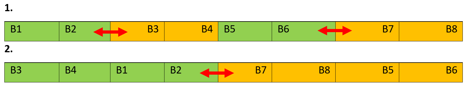
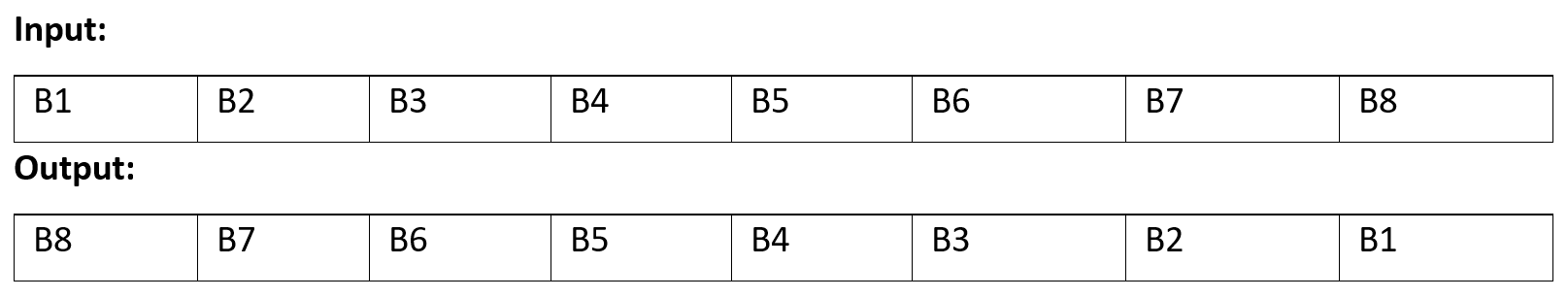
Following Data Types must be converted to Byte (Arrays) to be transferred:
- Date
- TOD
- DT
- String
Array of Byte must be filled in single bytes as well, because of the not accessible memory location.
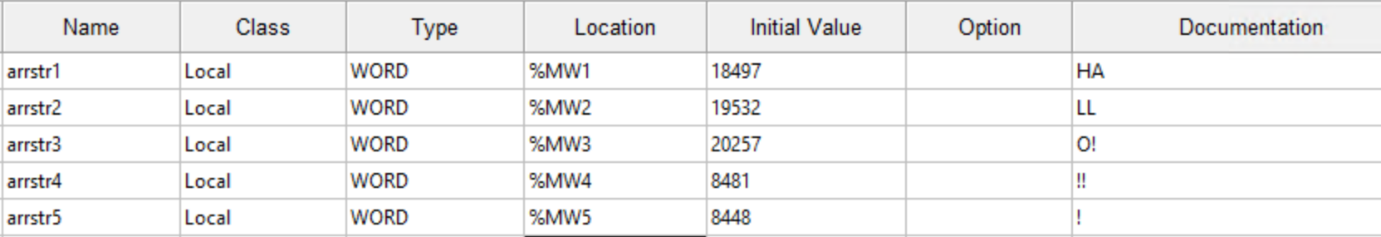
Example String:
Column Initial Value holds the converted ASCII values whereas column Documentation shows the single chars. The address for this "string" on the OpenPLC device would now be:
HoldingRegister.String:1025.5!SwapBytes!ASCII
Procedure for converting:
For converting strings to encodable values use a char to hexadecimal converter. For example, the char H equals 48 in ASCII encoding, char A equals 41, and so on... Convert all chars in this manner.
For the first register add 48 and 41 (the coded ascii values) and take the resulting decimal value, in this case 18497. Do this for all registers. The "string" is now ready to be sent.
On the HumanOS® side, it is necessary to know which encoding the sender used, as well as the length. As mentioned, different interpretation of memory can also result to data operations. In the case of OpenPLC it is necessary to add a "SwapBytes", or else each register will have swapped chars.
Notice: You can also add 41 in front of 48 for first register, so that no data operation is necessary on the HumanOS® side, but don't forget that the active swap is then done on the modbus device side.
The procedure is the same for dates (Date, TOD, DT).
The length of data type string varies. When specifying the length, take the number of characters as length identifier. Example: ‘Hello’ : 5 chars * 1 bytes = 5 bytes (specifier)
White spaces, new lines, tabs and escape chars are not allowed and will terminate the string encoding at the point of appearance.
Memory Type
The device control provides different channels for memory:
| Memory Channel | Description |
|---|---|
| InputBit | Global Input Memory (1-bit) |
| CoilBit | Global Output Memory (1-bit) |
| InputRegister | Global Input Memory (16-bit) |
| HoldingRegister | Global Output Memory (16-bit) |
Memory Type Configuration
InputBit
The values can only be read or monitored. Writing is not possible.
| Address Example | Description | Data Type |
|---|---|---|
| InputBit.Boolean:0.6 | Reads 1 Bit from I 0.6 | System.Boolean |
CoilBit
The values can only be read or monitored. For writing, use the appropriate command.
| Address Example | Description | Data Type |
|---|---|---|
| CoilBit.Boolean:0.7 | Reads 1 Bit from Q 0.7 | System.Boolean |
InputRegister
The values can only be read or monitored. Writing is not possible.
| Address Example | Description | Data Type |
|---|---|---|
| InputRegister.Float32:100 | Reads 4 Bytes from I 100 | System.Float |
HoldingRegister
The values can only be read or monitored. For writing, use the appropriate command.
| Address Example | Description | Data Type |
|---|---|---|
| HoldingRegister.Int32:1 | Reads the value from Q 1 | System.Int32 |
Memory Type Configuration
See chapter 5.1.1 for the available data types.
Register Offset
The register offset is the actual address in the memory of the device. See chapter 2.6 for more information.
Specifier
The specifier defines a length or a specific memory location and is only needed when working with following data types:
| Data Type | Range |
|---|---|
| ByteArray | 1-240 |
| String | 1-240 |
| Boolean | 0-7 |
Data Operation
Different devices use different storage mechanisms so it may be necessary to transform some raw data. In case of this need, just add one of the following options with a "!" character to the end of your address, if the data in HumanOS® doesn't look like the one on the modbus device:
| Address Example | Description | Data Type |
|---|---|---|
| HoldingRegister.Int16:10!ReverseArray | Swaps the bytes of the value (Hi-Low Byte; e.g. can be necessary in case of endian difference) | EDataOperations |
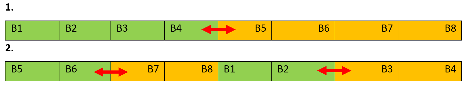
Possible Data operations (example shown with 64bit value, B = Byte):
| Operation | Description |
|---|---|
| SwapBytes | Swaps every byte pair |

| Operation | Description |
|---|---|
| SwapWords | Swaps every word pair |

| Operation | Description |
|---|---|
| SwapDWords | Swaps every double word pair |

| Operation | Description |
|---|---|
| SwapDWordsAndWords | Swaps every double word pair and after that every word pair |
| Operation | Description |
|---|---|
| SwapWordsAndDWords | Swaps every word pair and after that every double word pair |
| Operation | Description |
|---|---|
| ReverseArray | Reverses the data byte order |
String Encoding
Since modbus can only transfer raw data, the encoding type must be known by the receiving system. To negate this, just add a "!" character at the very end of your address (even after data operations if you have those active). After the exclamation mark add one of the following encodings:
| Address Example | Description | Data Type |
|---|---|---|
| HoldingRegister.String:10.10!ANSI | Encodes a string with ANSI and not with the default system setting | EStringEncodingOptions |
| HoldingRegister.String:10.10!UTF8 | Encodes a string with UTF8 and not with the default system setting | EStringEncodingOptions |
| HoldingRegister.String:10.10!UTF32 | Encodes a string with UTF32 and not with the default system setting | EStringEncodingOptions |
| HoldingRegister.String:10.10!Unicode | Encodes a string with Unicode and not with the default system setting | EStringEncodingOptions |
| HoldingRegister.String:10.10!ASCII | Encodes a string with ASCII and not with the default system setting | EStringEncodingOptions |
If the characters displayed are not equal to the expected, a data operation might be necessary as well.
Defining an Address and choosing the register
This example shows how to define an address. The example is shown with a Modbus TCP device manual. Any other address is configured in the same manner. The picture shows the address:
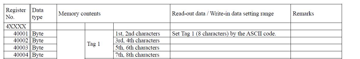
The address start from zero so there will always be a 1 byte offset. To read Tag 1 the address must look like this: HoldingRegister.String:0.2
With this address we will read the first 4 bytes with default system encoding and no data operations.
The following table shows the register ranges and their HumanOS® pendants:
| Register range | HumanOS® address name | Known as | Access |
|---|---|---|---|
| 00001 - 09998 | CoilBit | Coils | R/W |
| 10001 - 10998 | InputBit | Discrete Inputs | R |
| 30001 - 39998 | InputRegister | Input Registers | R |
| 40001 -- 49998 (105536) | HoldingRegister | Holding Registers | R/W |
Troubleshooting
Q: Why cant I connect to the PLC?
A: Check if pinging of the specified Endpoint is possible and if the Endpoint is supported.
Q: Why are my values are not shown as expected?
A:. See chapter 5.6 for information on data operation, the value is not converted in the right manner. Try different operations until the value is as expected.