Modbus TCP Control Driver Configuration
Plugin Configuration
The plugin configuration file is named settings.json located in <install directory>\Config\HumanOS.UHAL.ModbusTcpControl\. It contains all global settings of the plugin.
See Generic Plugin Configuration for more details.
The plugin is a polling-based plugin. The performance depends on the following factors:
- Location of the HumanOS® Runtime Host (from a network view, place as near as possible to the PLC)
- Number of TCP connections available for the Driver to the device
Plugin Configuration Extension
The FANUC Plugin extends the Generic Plugin Configuration with
- Sub Task processing
- Task Processor Memory Assignment
- Alarm and Event Settings
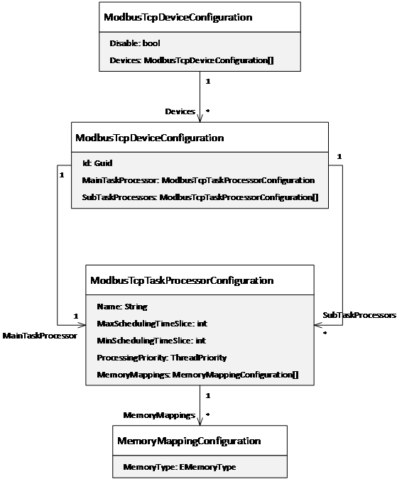
Figure 1: Configuration model of the Modbus TCP Plugin
Extension: Sub Task Processor
The configuration contains one or more task processors (threads) that handle different facets of the MODBUS control driver, like:
- Memory management (command, read, write and monitoring)
- Alarm and event management
At least one processor is needed. It is called MainTaskProcessor.
Additionally, different sub task processors can be added named
SubTaskProcessor. They allow to manage specific facets of the driver
in parallel. Several tasks can be predefined and added to the
processors.
Extension: Task Processor Memory Assignment
By default, all memory types are mapped to the main task processor. The memory mapping helps to assign the memory type address to another task processor. This helps to distribute the data processing load to different tasks (threads).
Note that if two task processors use the same memory mapping, the workload is split among these processors.
| Attribute | Description | Data Type |
|---|---|---|
| MemoryType | Memory type of the assigned memory. This setting is optional. If empty, all memory types of the memory base are handled by this processor. | EMemoryType |
Following example assigns the "Alarming" MemoryType to the SubTaskProcessor "Alarming":^
{
  "Name": "AlarmEventProcessor",
  "ProcessingPriority": "Normal",
  "MaxSchedulingTimeSlice": 500,
  "MinSchedulingTimeSlice": 100,
  "MemoryMappings": [
    {
      "MemoryType": "Alarming"
    }
  ]
}
Use the processing priority setting carefully!! Impropriate settings may cause high processor loads and could slow down the overall system performance. We recommend that only one of the processors is set to “Highest”.
Extension: Alarm and Event Handling
It is recommended to use a separate task processor for alarming and OEM message mapping.
For alarm reading, see Alarm Address.
Example
Following example shows a configuration of two task processors. The "MainTaskProcessor" handles the commanding, reading, writing and monitoring or all memories within the device. The "AlarmEventProcessor" manages the alarm and events.
{
  "Disabled": false,
  "Devices": [
    {
      "MainTaskProcessor": {
        "Name": "Main TaskProcessor",
        "ProcessingPriority": "Highest",
        "MaxSchedulingTimeSlice": 5,
        "MinSchedulingTimeSlice": 1
      },
      "SubTaskProcessors": [
        {
          "Name": "AlarmEventProcessor",
          "ProcessingPriority": "Normal",
          "MemoryMappings": [
            {
              "MemoryType": "Alarming"
            }
          ]
        }
      ]
    }
  ]
}
Device Information File
The device information file is used to configure the access devices by MODBUS protocol. It contains:
Id: unique device id (GUID), which MUST match the device license id.DriverId:4a06a655-36c2-4430-ae27-aaaa4a431395Address: Connection address- Data Access
- Alarm Events
See Device Information Model for more details.
Connection Address for Modbus TCP
The Address for Modbus TCP connections must be provided like following:
| Name | Description | Example |
|---|---|---|
| Address | IP address | address=10.256.35.32 |
| Port | Tcp Port | port=502 |
| SlaveId | Modbus Slave ID | slaveid=1 |
All three parameters are used as the address string, separated by semicolons.
Example: address=10.256.35.32;port=502;slaveid=1
Connection Address for Modbus RTU
If the RTU connection is to be used, the Property "ConnectionType" must be set in the device root node.
It's value must be "Rtu".
The Address for Modbus RTU connections must be provided like following:
| Name | Description | Example |
|---|---|---|
| Address | COM Address | address=COM3 |
| SlaveId | Modbus Slave ID | slaveid=1 |
For Windows machines, the COM resource is specified as the address.
Example: COM3
For Linux machines, the address is the path to the COM interface.
Example: /dev/ttyRS485
Both parameters are used for the address string, separated by a semicolon.
Example: address=/dev/ttyRS485;slaveid=1
The following additional connection properties can be set in the device model as property of the device root node:
| Name | Description | Data Type | Possible Values | Default Value |
|---|---|---|---|---|
| RtuTimeout | Timeout for the Rtu connection in milliseconds | System.Int32 | 50 | |
| BaudRate | Connection baud rate | System.Int32 | 115200 | |
| DataBits | Number of data bits | System.Int32 | 5, 6, 7, 8 | 8 |
| StopBits | Number of stop bits | System.String | 0, 1, 1.5, 2 | 1 |
| Parity | Serial port parity | System.String | none, even, mark, odd, space | none |
Property MemorySizes
To ensure a correct functioning, each Element which is accessed on the device (e.g. Register, Input, Output, etc...) must be declared with its maximum accessible size. Since the driver always fetches more than the declared data, it is crucial to set its register limits. This will then be added to the Device Properties. The default block size fetched is 120 + 3 (256 bytes) for 16-bit registers and 1992 + 8 for 1-bit registers (250 bytes).
Example for OpenPLC:
{
  "Name": "MemorySizes",
  "Value": "InputBit:*=799\nCoilBit:*=799\nInputRegister:*=1023\nHoldingRegister:*=8191"
}
Property PageSizes
Not all devices support transfers of 256 bytes at once. If the device only supports 64 bytes, then the below example fits the need:
Example for Device:
{
  "Name": "PageSizes",
  "Value": "InputBit=248\nCoilBit=248\nInputRegister=29\nHoldingRegister=29"
}
In the example above, the settings are in bits for InputBit and CoilBit, and in words for InputRegister and HoldingRegister. Insert this as Device Property, if nothing is declared the values listed in chapter Property MemorySizes are used.
Modbus TCP Memory Locations and Sizes
This data is device specific. The example shown below is valid for OpenPLC!
As mentioned, these offsets and data sizes are device dependent. For example, on an OpenPLC looks like this:
| Memory Type | Range | Example | Modbus memory offset |
|---|---|---|---|
| InputBit | I0.0 – I99.7 | InputBit.Boolean:1.0 = I1.0 | 0 |
| CoilBit | Q0.0 – Q99.7 | CoilBit.Boolean:2.2 = Q2.2 | 0 |
| InputRegister | IW0 - IW1023 | InputRegister.UInt16:10 = IW10 | 0 |
| HoldingRegister | MW1024 - MW2047 / DW2048- DW4095 / LW4096 - LW8191 | HoldingRegister. UInt16:1024 = MW0; HoldingRegister. UInt8:1025 = MW1; HoldingRegister.Float32:2048 = DW1; HoldingRegister. UInt32:2050 = DW2; HoldingRegister.Float64:2048 = LW1; HoldingRegister. UInt64:2052 = LW2 | 1024(16-bit) /2048(32-bit) /4096(64-bit) |
As seen the value which is stored in the holding registers or input registers is always 16 bits long, despite the data type.
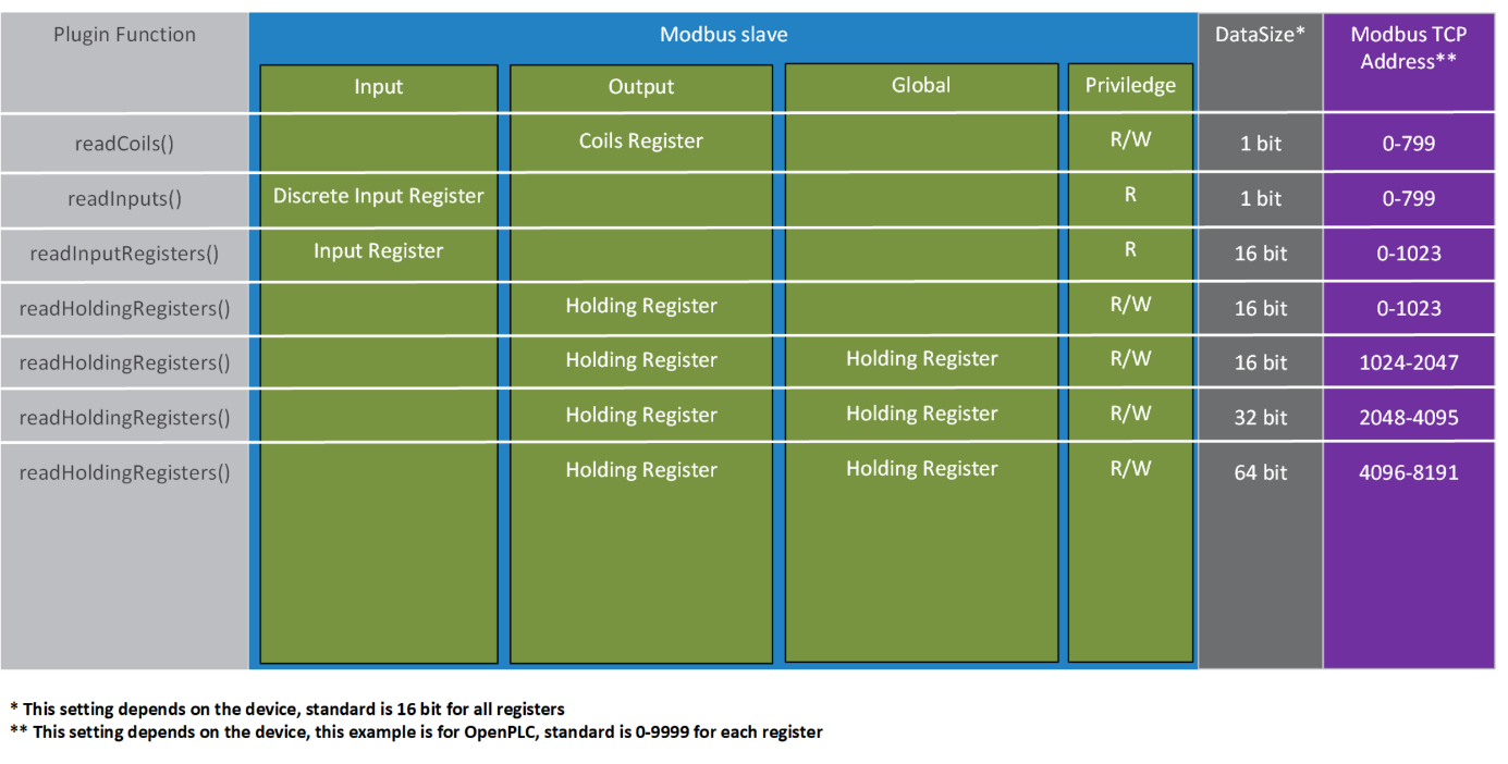
Registers explained
As seen in the chapters before, modbus has different registers. From a data type view, there are only two different registers: a bitwise and a 16-bit register.
The InputBitRegister and CoilBitRegister can only be addressed bitwise.
The InputRegister and HoldingRegister are 16-bit registers, which means they can hold all data types supported. For data types bigger than 16-bit like double words (UInt32), two or more registers must be combined.
In newer modbus devices, these ranges are declared (see image in previous chapter).
If a double word value is needed the definition on the different platforms looks like this (openplc example):
Definition programming software plc: %DW0
Definition HumanOS® Address: Holdingregister.UInt32:2048
The next address would look like this:
Definition programming software plc: %DW1
Definition HumanOS® Address: Holdingregister.UInt32:2050
Keep in mind that the counting of the HumanOS® address is dependent on the absolute offset of the modbus device, so as shown, if two combined registers are used, the offset is raised by 2, for 64-bit combined values by 4.
For values lower than 16-bit e.g. byte (UInt8) the used memory space is still 16-bit, the offset is raised by one.
Calculating the maximum Memory Size
If the maximum memory size of the target is unknown or it is not necessary to fetch that much data, the maximum memory size per target can be calculated like following:
Search for the address with the highest offset per target. Calculate the maximum target range with help of the data type.
Example Address: HoldingRegister.Float32:14

Example
{
  "Id": "7ea0317f-8f83-4e3e-a822-7498de01240f",
  "Name": "OpenPLC",
  "DriverId": "4a06a655-36c2-4430-ae27-aaaa4a431395",
  "Address": "address=10.196.24.11;port=502;slaveId=1",
  "Properties": [
    {
      "Name": "MemorySizes",
      "Value": "InputBit:*=799\nCoilBit:*=799\nInputRegister:*=1023\nHoldingRegister:*=8191"
    }
  ],
  "DataNodes": [
    {
      "Id": "e7c89c04-ff87-4951-95fa-6be81a29442d",
      "Name": "input00",
      "DataClass": "Event",
      "DataType": "System.Boolean",
      "Address": "InputBit.Boolean:0.0",
      "Access": {
        "Read": true,
        "Receive": true
      },
      "HistoryMode": {
        "Retention": 100,
        "SamplingRate": 2000
      }
    },
    {
      "Id": "14AE9CB7-6155-46EB-9A8D-8C859A75E7C8",
      "Name": "output00",
      "DataClass": "Event",
      "DataType": "System.Boolean",
      "Address": "CoilBit.Boolean:0.0",
      "Access": {
        "Read": true,
        "Receive": true
      },
      "HistoryMode": {
        "Retention": 100,
        "SamplingRate": 2000
      }
    },
    {
      "Id": "99CBDAB9-D5DC-470A-85F4-71EBB177C0AF",
      "Name": "inputreg",
      "DataClass": "Event",
      "DataType": "System.UInt16",
      "Address": "InputRegister.UInt16:0",
      "Access": {
        "Read": true,
        "Receive": true
      },
      "HistoryMode": {
        "Retention": 100,
        "SamplingRate": 2000
      }
    },
    {
      "Id": "04E7DEDE-2D32-4CD7-9573-FF895BF7E550",
      "Name": "qw1",
      "DataClass": "Event",
      "DataType": "System.UInt32",
      "Address": "HoldingRegister.UInt32:1",
      "Access": {
        "Read": true,
        "Receive": true
      },
      "HistoryMode": {
        "Retention": 100,
        "SamplingRate": 2000
      }
    }
  ]
}