Modbus Data Access
This chapter outlines all possible native addresses. These addresses must be configured within the device configuration.
Format
A native Modbus TCP address has following format:
{memory type}.{data type}:{Register Offset} + {Specifier (optional)} + {Data Operation (optional)} + {String Encoding (optional)}
Example:
HoldingRegister.Boolean:118.6
This will read 1 Bit (Boolean) of HoldingRegister with Offset 118 and Specifier 6 (Bit 6).
Value Conversion and Supported Data Types
Keep in mind that there are data type conversions resulting from different platforms (brackets mark the section in the config example):
| Device Data Type | HumanOS® Data Type (Address) | C# Data Type (DataType) |
|---|---|---|
| USInt | UInt8 | System.Byte |
| UInt | UInt16 | System.UInt16 |
| UDInt | UInt32 | System.UInt32 |
| ULInt | UInt64 | System.UInt64 |
| Word | Int16 | System.Int16 |
| DWord | Int32 | System.Int32 |
| LWord | Int64 | System.Int64 |
| Real | Float32 | System.Float |
| LReal | Float64 | System.Double |
| Array of Byte | ByteArray | System.Byte[] |
| Bool | Boolean | System.Boolean |
| String | String | System.String |
Following Data Types must be converted to Byte (Arrays) to be transferred:
- Date
- TOD
- DT
Array of Byte must be filled in single bytes as well, because of the not accessible memory location.
Example String:
Column Initial Value holds the converted ASCII values whereas column Documentation shows the single chars. The address for this "string" on the OpenPLC device would now be:
HoldingRegister.String:1025.5!SwapBytes!ASCII
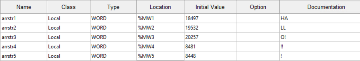
Procedure for converting:
For converting strings to encodable values use a char to hexadecimal converter. For example, the char H equals 48 in ASCII encoding, char A equals 41, and so on... Convert all chars in this manner.
For the first register add 48 and 41 (the coded ascii values) and take the resulting decimal value, in this case 18497. Do this for all registers. The "string" is now ready to be sent.
On the HumanOS® side, it is necessary to know which encoding the sender used, as well as the length. As mentioned, different interpretation of memory can also result to data operations. In the case of OpenPLC it is necessary to add a "SwapBytes", or else each register will have swapped chars.
Notice: You can also add 41 in front of 48 for first register, so that no data operation is necessary on the HumanOS® side, but don't forget that the active swap is then done on the modbus device side.
The procedure is the same for dates (Date, TOD, DT).
The length of data type string varies. When specifying the length, take the number of characters as length identifier. Example: ‘Hello’ : 5 chars * 1 bytes = 5 bytes (specifier)
White spaces, new lines, tabs and escape chars are not allowed and will terminate the string encoding at the point of appearance.
Memory Type
The device control provides different channels for memory:
| Memory Channel | Description |
|---|---|
| InputBit | Global Input Memory (1-bit) |
| CoilBit | Global Output Memory (1-bit) |
| InputRegister | Global Input Memory (16-bit) |
| HoldingRegister | Global Output Memory (16-bit) |
| System | Driver specific information |
Memory Type Configuration
InputBit
The values can only be read or monitored. Writing is not possible.
| Address Example | Description | Data Type |
|---|---|---|
| InputBit.Boolean:0.6 | Reads 1 Bit from I 0.6 | System.Boolean |
CoilBit
The values can only be read or monitored. For writing, use the appropriate command.
| Address Example | Description | Data Type |
|---|---|---|
| CoilBit.Boolean:0.7 | Reads 1 Bit from Q 0.7 | System.Boolean |
InputRegister
The values can only be read or monitored. Writing is not possible.
| Address Example | Description | Data Type |
|---|---|---|
| InputRegister.Float32:100 | Reads 4 Bytes from I 100 | System.Float |
HoldingRegister
The values can only be read or monitored. For writing, use the appropriate command.
| Address Example | Description | Data Type |
|---|---|---|
| HoldingRegister.Int32:1 | Reads the value from Q 1 | System.Int32 |
System
The values can only be read or monitored. Writing data to this memory is not possible.
| Address Example | Description | Data Type |
|---|---|---|
| System.Int32:1 | Returns the available flag. 0 = offline, 1 = driver is connected | System.Int32 |
| System.Int32:2 | Returns the sign of life toggle bit, toggles with 1Hz when connected | System.Int32 |
Memory Type Configuration
The following memory types are available to read with the modbus driver
| Memory type | C# Data Type |
|---|---|
| UInt8 | System.Byte |
| UInt16 | System.UInt16 |
| UInt32 | System.UInt32 |
| UInt64 | System.UInt64 |
| Int16 | System.Int16 |
| Int32 | System.Int32 |
| Int64 | System.Int64 |
| Float32 | System.Float |
| Float64 | System.Double |
| ByteArray | System.Byte[] |
| Boolean | System.Boolean |
| String | System.String |
Register Offset
The register offset is the actual address in the memory of the device. See Registers explained for more information.
Specifier
The specifier defines a length or a specific memory location and is only needed when working with following data types:
| Data Type | Range |
|---|---|
| ByteArray | 1-240 |
| String | 1-240 |
| Boolean | 0-7 |
Data Operation
Different devices use different storage mechanisms so it may be necessary to transform some raw data. In case of this need, just add one of the following options with a "!" character to the end of your address, if the data in HumanOS® doesn't look like the one on the modbus device: The type of data operation is EDataOperations.
The possible data operations are described in the following subchapters. (examples shown with 64bit value, B = Byte):
Example:
HoldingRegister.Int16:10!ReverseArray
This address example swaps the bytes of the value (Hi-Low Byte; e.g. can be necessary in case of endian difference)
None
No data operation
SwapBytes
Swaps every byte pair

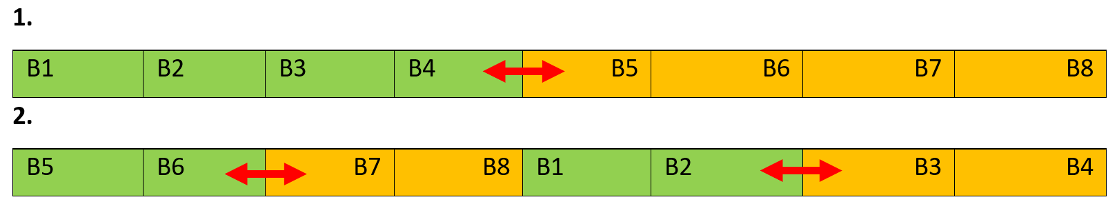
SwapWords
Swaps every word pair

SwapDWords
Swaps every double word pair

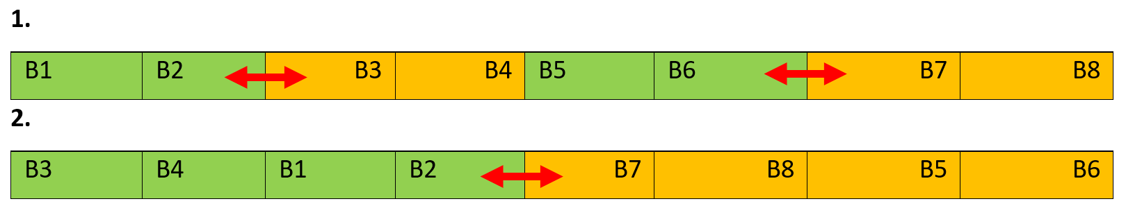
SwapDWordsAndWords
Swaps every double word pair and after that every word pair
SwapWordsAndDWords
Swaps every word pair and after that every double word pair
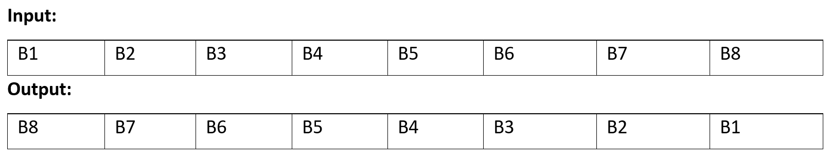
ReverseArray
Reverses the data byte order
String Encoding
Since modbus can only transfer raw data, the encoding type must be known by the receiving system. To negate this, just add a "!" character at the very end of your address (even after data operations if you have those active). After the exclamation mark add one of the following encodings:
| Address Example | Description | Data Type |
|---|---|---|
| HoldingRegister.String:10.10!ANSI | Encodes a string with ANSI and not with the default system setting | EStringEncodingOptions |
| HoldingRegister.String:10.10!UTF8 | Encodes a string with UTF8 and not with the default system setting | EStringEncodingOptions |
| HoldingRegister.String:10.10!UTF32 | Encodes a string with UTF32 and not with the default system setting | EStringEncodingOptions |
| HoldingRegister.String:10.10!Unicode | Encodes a string with Unicode and not with the default system setting | EStringEncodingOptions |
| HoldingRegister.String:10.10!ASCII | Encodes a string with ASCII and not with the default system setting | EStringEncodingOptions |
If the characters displayed are not equal to the expected, a data operation might be necessary as well.
Defining an Address and Choosing the Register
This example shows how to define an address. The example is shown with a Modbus TCP device manual. Any other address is configured in the same manner. The picture shows the address:
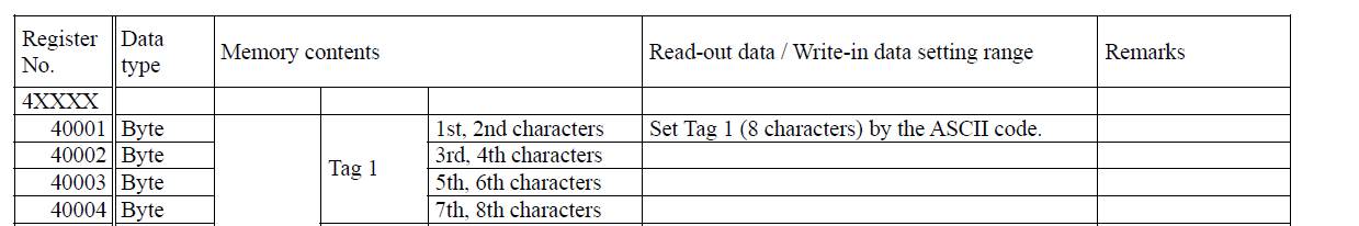
The address start from zero so there will always be a 1 byte offset. To read Tag 1 the address must look like this: HoldingRegister.String:0.2
With this address we will read the first 4 bytes with default system encoding and no data operations.
The following table shows the register ranges and their HumanOS® pendants:
| Register range | HumanOS® address name | Known as | Access |
|---|---|---|---|
| 00001 - 09998 | CoilBit | Coils | R/W |
| 10001 - 10998 | InputBit | Discrete Inputs | R |
| 30001 - 39998 | InputRegister | Input Registers | R |
| 40001 -- 49998 (105536) | HoldingRegister | Holding Registers | R/W |
Troubleshooting
Q: Why cant I connect to the PLC?
A: Check if pinging of the specified Endpoint is possible and if the Endpoint is supported.
Q: Why are my values are not shown as expected?
A:. See Data Operation for information on data operation, the value is not converted in the right manner. Try different operations until the value is as expected.