Siemens S7 Control Driver Configuration
Plugin Configuration
The plugin configuration file is named settings.json located in <install directory>\Config\HumanOS.UHAL.BluetoothDeviceDriver\. It contains all global settings of the plugin.
See Generic Plugin Configuration for more details.
Plugin Configuration Extension
The S7 Plugin extends the Generic Plugin Configuration with
- Task Processor Memory Assignment
- Sub Task processing
- Alarm and Event Settings
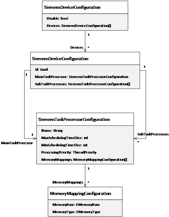
Figure 1: Configuration mode of the plugin
Extension: Sub Task Processor
It contains the task processors (threads) that handle different facets of the Siemens S7 control driver, like:
- Memory management (command, read, write and monitoring)
- Alarm and event management
At least one processor is needed. It is called MainTaskProcessor.
Additionally, different sub task processors can be added named
SubTaskProcessor. They allow to manage specific facets of the driver
in parallel. Several tasks can be predefined and added to the
processors.
Extension: Task Processor Memory Assignment
By default, all memory bases are mapped to the main task processor. The memory mapping helps to assign the memory base address to another task processor. This helps to distribute the data processing load to different tasks (threads).
Note that if two task processors use the same memory mapping, the workload is split among these processors.
| Attribute | Description | Data Type |
|---|---|---|
| MemoryBase | Base address of the assigned memory | EMemoryBase |
| MemoryType | Memory type of the assigned memory. This setting is optional. If empty, all memory types of the memory base are handled by this processor. | EMemoryType |
Following example assigns the "Alarming" MemoryType to the SubTaskProcessor "Alarming":
{
  "SubTaskProcessors": [
    {
      "Name": "AlarmEventProcessor",
      "ProcessingPriority": "Normal",
      "MemoryMappings": [
        {
          "MemoryBase": "Plc1",
          "MemoryType": "Alarming"
        }
      ]
    }
  ]
}
Use the processing priority setting carefully!! Impropriate settings may cause high processor loads and could slow down the overall system performance. We recommend that only one of the processors is set to “Highest”.
Extension: Alarm and Event Handling
It is recommended to use a separate task processor for alarming and OEM message mapping.
For alarm configurations, see Alarm Address.
Following example shows a configuration of multiple configurations with multiple task processors. In the first configuration that is bound to all detected Siemens S7 devices by default, the "MainTaskProcessor" handles the commanding, reading, writing and monitoring or all memories within the device. The "Alarming" sub processor manages the alarm and events.
The second configuration which is commented with "Configuration for S7-400", has 7 sub processors which share the load of the MainTaskProcessor. So eight processors handle the commanding, reading, writing and monitoring or all memories within the device and a further one the alarming.
The second configuration also opens 8+1 TCP connections. Remember: Each processor opens one TCP connection, so make sure the Siemens CPU can handle the connections.
{
  "Disabled": false,
  "Devices": [
    {
      "MainTaskProcessor": {
        "Name": "Main TaskProcessor",
        "ProcessingPriority": "Highest",
        "MaxSchedulingTimeSlice": 5,
        "MinSchedulingTimeSlice": 1
      },
      "SubTaskProcessors": [
        {
          "Name": "AlarmEventProcessor",
          "ProcessingPriority": "Normal",
          "MemoryMappings": [
            {
              "MemoryBase": "Plc1",
              "MemoryType": "Alarming"
            }
          ]
        }
      ]
    },
    {
      "Id": "ECE37FDF-4862-4543-AF23-48FFDB8203C7",
      "MainTaskProcessor": {
        "Name": "Main TaskProcessor",
        "ProcessingPriority": "Normal",
        "MaxSchedulingTimeSlice": 20,
        "MinSchedulingTimeSlice": 5
      },
      "SubTaskProcessors": [
        {
          "Name": "TaskProc1",
          "ProcessingPriority": "Normal",
          "MaxSchedulingTimeSlice": 20,
          "MinSchedulingTimeSlice": 5
        },
        {
          "Name": "TaskProc2",
          "ProcessingPriority": "Normal",
          "MaxSchedulingTimeSlice": 20,
          "MinSchedulingTimeSlice": 5
        },
        {
          "Name": "TaskProc3",
          "ProcessingPriority": "Normal",
          "MaxSchedulingTimeSlice": 20,
          "MinSchedulingTimeSlice": 5
        }
      ]
    }
  ]
}
Device Information File
The device information file is used to configure the access to the Bluetooth devices. It contains:
Id: unique device id (GUID), which MUST match the device license id.DriverId:11034AA5-13C7-4D05-83E0-361BC816E779Address: Connection address- Data Access
- Alarm Events
See Device Information Model for more details.
Connection Address
The Siemens S7 Driver needs an Endpoint specification. This means, the topology defined in the Hardware Editor in the Siemens IDE (S7 Classic or TIA Portal) must be provided as connection Information. Either the CP (if used) or the PLC must be provided as Slot Number.
The Address for Siemens S7 Control must be provided like following:
| Name | Description | Example |
|---|---|---|
| Address | PLC Type, IP, Rack and Slot | Cpu=S7300;Address=192.168.44.62;Rack=0;Slot=2 |
This information is contained by the device configuration.
Property TcpTimeout
Network Timeout property in Milliseconds, default is 10s. Example 5s:
{
  "Name": "TcpTimeout",
  "Value": 5000,
  "DataType": "System.Int32"
}
Property PageDataLoggingOn
This only works for page based items. Reading variables does not yield any results.
Logs every successful page reading event to the log file, default property value (System.Boolean) is false.
Sample output for an alarm and a memory address:
AlarmEvent: Successfully read from DB='972' with Size='30' for Page Plc1.DataBlock.ByteArray:972.0[30].0 Data: 0 0 0 0 0 0 0 0 0 0 0 0 0 0 0 0 0 0 0 0 0 0 0 0 0 0 0 0 0 0
MemoryPage: Successfully read from DB='130' with Size='18' for Page Plc1.DataBlock.Uint8:130.0.0 Data: 64 224 0 0 64 224 0 0 69 122 0 0 0 0 69 122 0 0
This can generate huge log files. Only activate if necessary.
Property TaskProcMonitoringOn
Logs the state of each page reader per processor once a minute, default property value is false.
Sample output for an alarm and a memory processor:
Status for Processor 'MainTaskProcessor'
'26' PageUpdaters
	|__ 844429232832512 - Plc1.DataBlock.Uint8:118.0.0 Running: True
	|__ 844429232898048 - Plc1.DataBlock.Uint8:119.0.0 Running: True
	|__ 844429232963584 - Plc1.DataBlock.Uint8:120.0.0 Running: True
	|__ 844429233094656 - Plc1.DataBlock.Uint8:122.0.0 Running: True
	|__ 844429233225728 - Plc1.DataBlock.Uint8:124.0.0 Running: True
	|__ 844429233291264 - Plc1.DataBlock.Uint8:125.0.0 Running: True
	|__ 844429233422336 - Plc1.DataBlock.Uint8:127.0.0 Running: True
	|__ 844429233618944 - Plc1.DataBlock.Uint8:130.0.0 Running: True
	|__ 844429233684480 - Plc1.DataBlock.Uint8:131.0.0 Running: True
	|__ 844429233750016 - Plc1.DataBlock.Uint8:132.0.0 Running: True
	|__ 844429234012160 - Plc1.DataBlock.Uint8:136.0.0 Running: True
	|__ 844429234077696 - Plc1.DataBlock.Uint8:137.0.0 Running: True
	|__ 844429234143232 - Plc1.DataBlock.Uint8:138.0.0 Running: True
	|__ 844429234536448 - Plc1.DataBlock.Uint8:144.0.0 Running: True
	|__ 844429234208768 - Plc1.DataBlock.Uint8:139.0.0 Running: True
	|__ 844429234274304 - Plc1.DataBlock.Uint8:140.0.0 Running: True
	|__ 844429234339840 - Plc1.DataBlock.Uint8:141.0.0 Running: True
	|__ 844429234405376 - Plc1.DataBlock.Uint8:142.0.0 Running: True
	|__ 844429234470912 - Plc1.DataBlock.Uint8:143.0.0 Running: True
	|__ 844429234601984 - Plc1.DataBlock.Uint8:145.0.0 Running: True
	|__ 844429234667520 - Plc1.DataBlock.Uint8:146.0.0 Running: True
	|__ 844429235847168 - Plc1.DataBlock.Uint8:164.0.0 Running: True
	|__ 844429237026816 - Plc1.DataBlock.Uint8:182.0.0 Running: True
	|__ 844429237092352 - Plc1.DataBlock.Uint8:183.0.0 Running: True
	|__ 844429237616640 - Plc1.DataBlock.Uint8:191.0.0 Running: True
	|__ 844429237682176 - Plc1.DataBlock.Uint8:192.0.0 Running: True
'0' AlarmEventUpdaters

Status for Processor 'Alarming'
'0' PageUpdaters
'3' AlarmEventUpdaters
	|__ Plc1/DB970 - Plc1.DataBlock.ByteArray:970.0[1] - Raise Running: True
	|__ Plc1/DB971 - Plc1.DataBlock.ByteArray:971.0[1] - Confirm Running: True
	|__ Plc1/DB972 - Plc1.DataBlock.ByteArray:972.0[30] - Standard Running: True
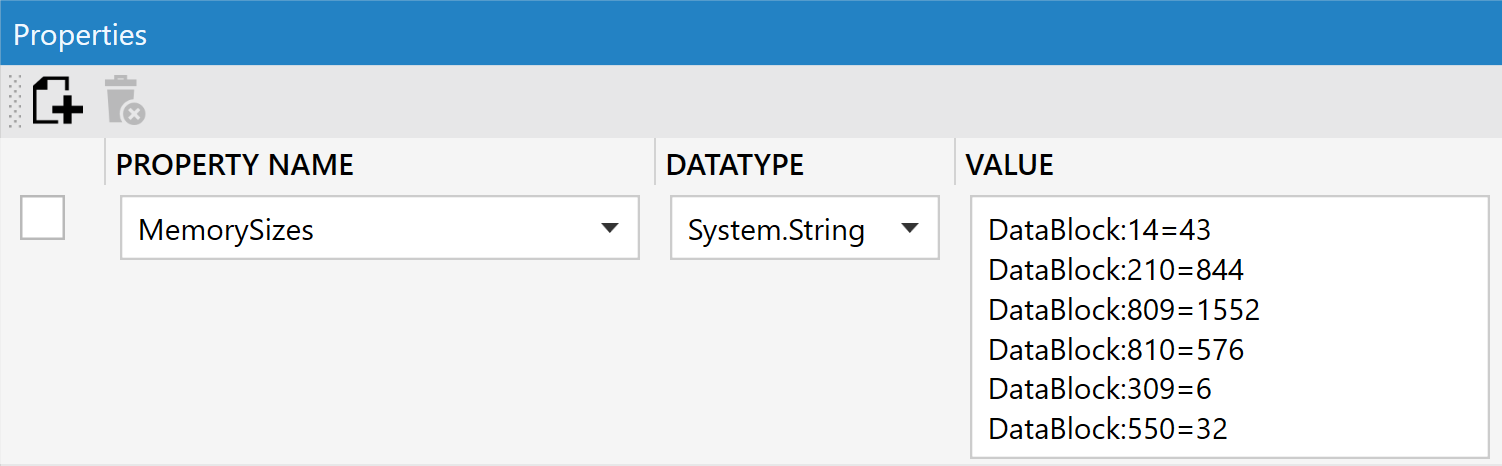
Property MemorySizes
The maximum fetched memory size of each Element which is accessed on the PLC (e.g. DataBlock, Input, Output, etc...) is calculated automatically. It is possible to override the maximum size by specifying the exact address. Wildcards (*) are treated weakest and will always be overriden. This will then be added to the Device Properties.
Examples:
Declare all data blocks with the maximum size of 60 bytes (0-59 accessible).
{
  "Name": "MemorySizes",
  "Value": "DataBlock:*=60"
}
Declare only data block 100 with the maximum size of 60 bytes (0-59 accessible).
{
  "Name": "MemorySizes",
  "Value": "DataBlock:100=60"
}
Declare all data blocks with the maximum size of 30 bytes (0-29 accessible) except data block 100 which is 60 bytes.
{
  "Name": "MemorySizes",
  "Value": "DataBlock:*=30\\nDataBlock:100=60"
}
Designer view example (device node properties):
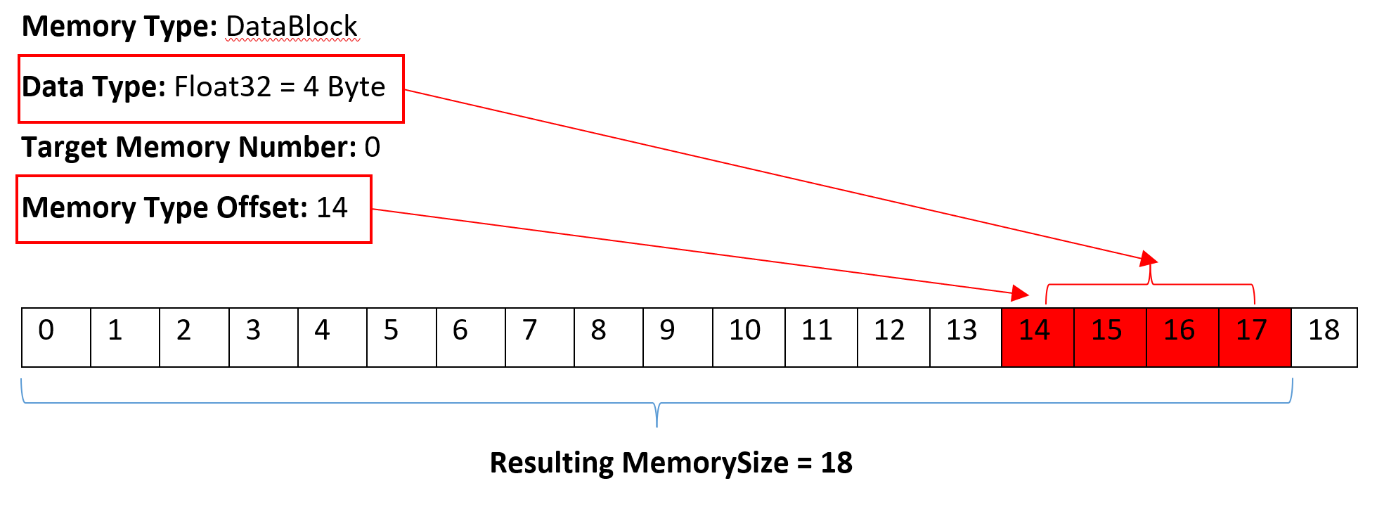
Calculating the Maximum Memory Size
If the maximum memory size of the target is unknown or it is not necessary to fetch that much data, the maximum memory size per target can be calculated like following:
Search for the address with the highest offset per target.¨
Calculate the maximum target range with help of the data type.
Example Address: Plc1.DataBlock.Float32:0.14