Siemens S7 Alarm and Events
Alarm Address
The Address for the alarms is following:
| Address | Description | Data Type |
|---|---|---|
Plc1.OEMAlarmEvent:0 | System Alarm and operator message reader. | TAlarmEvent[] |
Messages are not acknowledged by the HumanOS® IoT Platform. Typically, this is done by the machine component when its associated reset action is activated.
Alarm Item
See the Operation Manual for the containing fields.
Alarm Tasks and Mapping
The driver supports PLC alarms by mapping source.
It is possible to declare multiple alarm sources (tasks) for one alarm address (pool).
This example shows three alarm sources with a mapping file:
{
  "AlarmEventPool": {
    "Id": "0efafbcd-447a-4fb6-900d-51affdc25e8f",
    "Name": "Alarming",
    "HistoryMode": {
      "Retention": 20,
      "SamplingRate": 2000
    },
    "Tasks": [
      {
        "Id": "66d0a44d-83e8-494d-9e15-5af16df60d55",
        "Name": "Alarm Messages",
        "Address": "Plc1.OEMAlarmEvent:0",
        "Properties": [
          {
            "Name": "MessageMappingFile",
            "Value": "Signallist.json"
          },
          {
            "Name": "MessageCount",
            "Value": 187,
            "DataType": "System.Int32"
          },
          {
            "Name": "StartAddress",
            "Value": "Plc1.DataBlock.ByteArray:970.0[47]"
          },
          {
            "Name": "MessageFormat",
            "Value": "BitMessage"
          },
          {
            "Name": "Message:Type",
            "Value": "Raise"
          }
        ]
      },
      {
        "Id": "f2280557-9806-414d-b002-aa3e30fb79b5",
        "Name": "Alarm Confirm Messages",
        "Address": "Plc1.OEMAlarmEvent:0",
        "Properties": [
          {
            "Name": "MessageMappingFile",
            "Value": "Signallist.json"
          },
          {
            "Name": "MessageCount",
            "Value": 187,
            "DataType": "System.Int32"
          },
          {
            "Name": "StartAddress",
            "Value": "Plc1.DataBlock.ByteArray:971.0[47]"
          },
          {
            "Name": "MessageFormat",
            "Value": "BitMessage"
          },
          {
            "Name": "Message:Type",
            "Value": "Confirm"
          }
        ]
      }
    ]
  }
}
| Accessor | Description |
|---|---|
| Id | Unique Id for each task |
| Name | A name for the task |
| Address | Alarm address (pool) |
| Property MessageMappingFile | The mapping file to load (copy to The mapping file to load - copy to .\Config\HumanOS.UHAL.SiemensS7Control\) |
| Property MessageCount | Amount of messages which are mapped (depends on the Property MessageFormat) |
| Property StartAddress | The corresponding source address with offset and length (depends on the Property MessageFormat) |
| Property MessageFormat | BitMessage or Channel32Message |
| Property Message:Type | Type of each message that occurs from this source |
A property which starts with Message: is attached as property to the alarm item (e.g. message) which means additional fields are added with this data and can be used later on.
Mapping means, the alarms and events are defined by the data given and not the data that the alarm source provides.
The mapping source must either be of type JSON and must be structured like this example:
{
  "Messages": [
    {
      "Id": 0,
      "AlarmType": "Alarm",
      "OemId": "Alarm 1",
      "Text": "PU Sammelfehler",
      "Properties": [
        {
          "Name": "MyProperty",
          "Value": "Some other info"
        },
        {
          "Name": "EnableRmq",
          "Value": "1"
        },
        {
          "Name": "EnableRest",
          "Value": "0"
        }
      ]
    }
  ]
}
| Accessor | Description |
|---|---|
| Id | Specifies the bit number (absolute) |
| AlarmType | Specifies the Alarm type, see Alarm Types in Alarm and Event Source |
| OemId | The Condition name of the alarm or event |
| Text | Specifies the message |
| Properties | Specify properties which are attached to this alarm or event and can later be accessed |
| Properties:Name | Property name |
| Properties:Value | Property value |
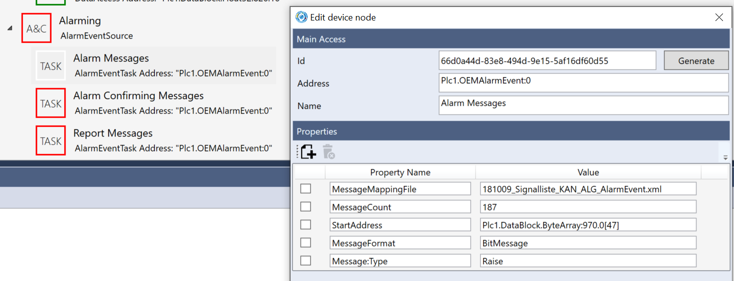
Example in the designer:
Calculation of MessageCount
The "MessageCount" together with the "MessageFormat" specifies the amount of data to be read.
| MessageFormat | Description |
|---|---|
| BitMessage | The entered value is divided by 8 and rounded to the next bigger number of 8*value to specify the number of bytes to be read, the raw value is mapped to the message file |
| Channel32Message | The entered value is multiplied by 4 to specify the number of bytes to be read, the raw value is mapped to the message file |
Bitmessage
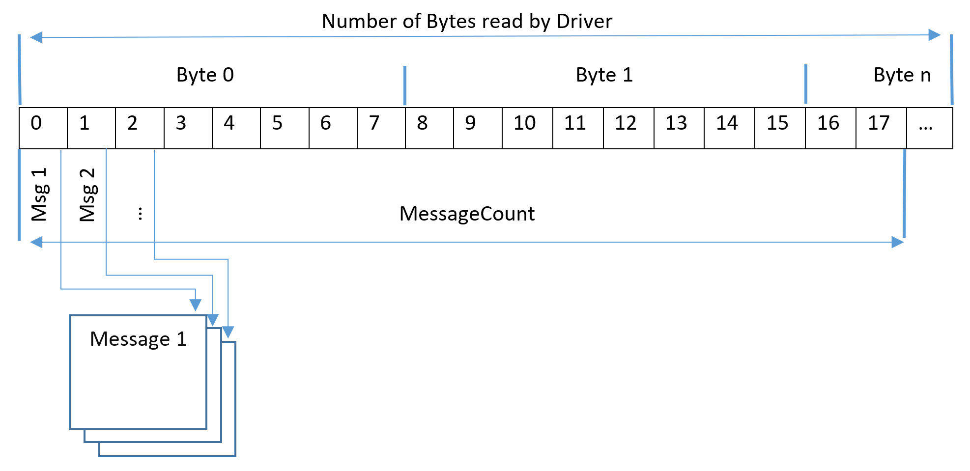
Examples BitMessage:
| Entered Value | Number of bytes read by driver | Mapped messages (bits) |
|---|---|---|
| 0 | 0 | 0 |
| 2 | 1 | 2 |
| 8 | 1 | 8 |
| 9 | 2 | 9 |
| 200 | 25 | 200 |
| 1056 | 132 | 1056 |
Channel32Messages
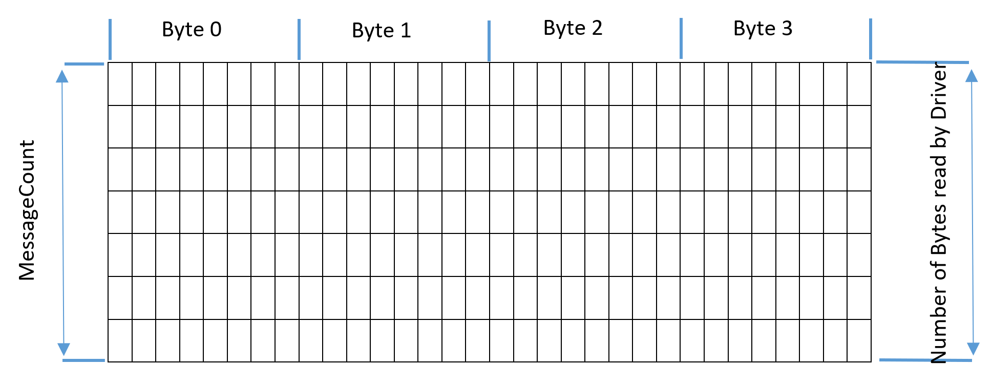
Each segment displays a bit and a bit equals a channel, so for example if there are 32 error LEDs on a device each segment could be one LED. The 32-bit channel messages allow bundling of errors of the same type. One error text will then be applied for all 32 bits, with the channel id automatically attached.
Examples Channel32Message:
| Entered Value | Number of byes read by driver | Mapped messages | Mapped bits |
|---|---|---|---|
| 0 | 0 | 0 | 0 |
| 1 | 4 | 1 | 32 |
| 4 | 16 | 4 | 128 |
| 9 | 36 | 9 | 288 |
| 16 | 64 | 16 | 512 |
| 33 | 132 | 33 | 1056 |
Calculation of StartAddress
The "StartAddress" specifies the source, offset and length of the data array.
It is possible and needed by Channel32Messages to specify a higher length than the "MessageCount". The suggestion is to calculate the "MessageCount" and adapt the value in the brackets to avoid conflicts.
BitMessage:
| Calculation | Example |
|---|---|
MessageCount / 8 -> round to next bigger whole number | 20/8=2.5 -> 3 Bytes |
Length * 8 | 3*8=24 Messages/Bits |
Channel32Message:
| Calculation | Example |
|---|---|
MessageCount * 4 | 10*4=40 Bytes |
Length / 4 | 40/4=10 Messages/Bits |
The address Plc1.DataBlock.ByteArray:972.0[48] means:
- Source:
DataBlock - DataType:
ByteArray - Source Number:
972 - Offset in byte:
0 - Length in byte:
48
Examples:
| Bracket Value (Array Length) | MessageCount | MessageFormat | Resulting Length in bytes |
|---|---|---|---|
| 1 | 1 | BitMessage | 1 |
| 4 | 1 | BitMessage | 1 |
| 16 | 16 | BitMessage | 2 |
| 16 | 128 | BitMessage | 16 |
| 4 | 1 | Channel32Message | 4 |
| 8 | 2 | Channel32Message | 8 |
| 132 | 2 | Channel32Message | 8 |